


In this project, we will learn and explore the interfacing of OLED (Organic Light-Emitting Diode) displays with the Raspberry Pi Pico W using the Arduino IDE. Due to their high contrast, and low power consumption, OLED displays have gained popularity for use in small-scale projects.
Previously, we have learned to interface OLED with ESP32 and built some projects like GPS Tracker, Soil Moisture Monitoring System, Heartbeat Monitoring System etc.
The Raspberry Pi Pico W is a microcontroller board based on the RP2040 chip, featuring a dual-core Arm Cortex-M0+ processor and abundant GPIO pins. We can easily program the Pico W by leveraging the Arduino IDE, taking advantage of its flexibility and compatibility with various hardware peripherals and a large library ecosystem. We will use the Arduino IDE ecosystem to display text on the OLED.
Combining the Raspberry Pico with an OLED display can be a solution for various small projects like displaying sensor data, and output values, creating a mini dashboard, and a lot more, this project will guide you through the process of setting up and utilizing an OLED display with the Pico W.
Components Required
- OLED Display 0.96 Inch I2C Interface
- Raspberry Pi Pico W Board
- Jumper Wires & Breadboard
SSD1306 OLED Display
SSD1306 OLED Display is an I2C display requiring only two interfacing pins. Since I2C is a widely used way of communication, making it easy to interface with microcontrollers and other devices.
The OLED displays are available in different sizes, but we use a generic SSD1306 driver IC and a 128*64 resolution-based display.
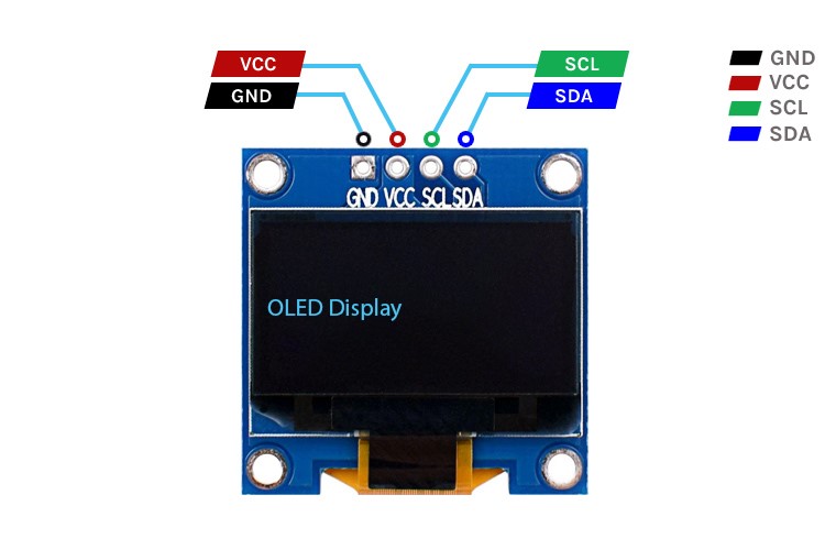
The connections of the OLED display include Four Terminals:
VCC: This pin is used to supply power to the display module. It works on 3.3V or 5V power supply input.
GND: This pin is connected to the ground (0V) of the power supply.
SDA: The Serial Data line (SDA) transfers bidirectional data between the microcontroller and the SSD1306 display. It connects to the SDA pin of the microcontroller or the I2C bus.
SCL: The Serial Clock line (SCL) is used for synchronizing the data transfer between the microcontroller and the SSD1306 display. It connects to the SCL pin of the microcontroller or the I2C bus.
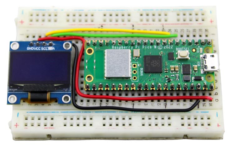
Circuit Diagram of Interfacing OLED with Raspberry Pi Pico W
By referring to the provided interfacing diagram, you will be able to establish the necessary connections effortlessly. While the Raspberry Pi Pico W board offers multiple I2C communication pins, the Arduino IDE internal libraries currently support only a single pair of default pins for I2C communication which is GP4 & GP5 IO.
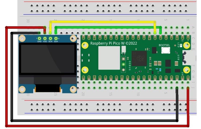
The Vcc or power pin of the OLED should be connected to the VBUS pin of the Raspberry Pi Pico W.
The GND of the OLED is connected to any Ground terminal of the Pico Board. Since there are various ground terminals on the board, you can use any of them.
The SDA terminal Pin is used for I2C communication which is connected to GP4 (#6th pin).
The SCL terminal pin is also for I2C communication which is connected to GP5 (#7th pin).
Arduino Code for interfacing OLED with Raspberry Pi Pico W
The Code initializes the OLED display, sets up the text properties, and displays the specified text on the OLED screen.
For interfacing the display with the Microcontroller board, firstly we need to define the necessary libraries including Adafruit_SSD1306.h and Adafruit_GFX.h.
The Adafruit_SSD1306 library is used to control an SSD1306-based OLED display with a resolution of 128x64 pixels, and Adafruit_GFX is a graphics library that provides common graphics functions to adjust display text size, font, color, and a lot more graphics.
Also, a Constructor of the Adafruit_SSD1306 class is created to interact with the OLED display with the name of “display” whose parameters are display width (128) pixels and height (64) pixels. A third parameter can also pass to the constructor, which is the Reset Pin Number but since our OLED module doesn’t have any reset pin terminal, we haven’t used the parameter.
#include <Adafruit_SSD1306.h>
#include <Adafruit_GFX.h>
Adafruit_SSD1306 display(128, 64);
Inside the setup() function:
- display.begin(SSD1306_SWITCHCAPVCC, 0x3C); initializes the display by specifying the power scheme (SSD1306_SWITCHCAPVCC) to turns-On the internal circuitry and the I2C address of the display (0x3C).
- display.clearDisplay(); clears the display buffer to make it completely blank.
- display.setTextColor(WHITE); setting the text color to white makes the background Dark while the black makes bright background.
- display.setTextSize(2); sets the text size to 2, making it larger. Using 1 will make the text small.
- display.setCursor(0, 0); sets the cursor position to the top-left corner of the display. The two parameters work as an X-axis and a Y-axis of the location of the text.
- display.println(); prints the specified text inside inverted commas. We use this function twice to adjust the word display according to the Screen.
- display.display(); the function pushes the display buffer to SSD1306 controller memory to display on to the OLED Screen.
void setup() {
  // Initialize the display
  display.begin(SSD1306_SWITCHCAPVCC, 0x3C);  // Address 0x3C for 128x32
  // Clear the display
  display.clearDisplay();
  display.setTextColor(WHITE);
  display.setTextSize(2);
  display.setCursor(0, 0);
  display.println("Raspberry Pi Pico W");
  display.println("with OLED display");
  display.display();
}
The loop() function, is called repeatedly but in this case, there is no need to repeatedly call any commands. So, the function will be kept blank.
void loop() {
  // Nothing to do here, just display the static text
}
Once the setup is done, it continuously displays the static text as there is no active functionality implemented in the loop.
Working of OLED with Raspberry Pi Pico W
To upload code to the Raspberry Pi Pico W, it is necessary to install the board library in your Arduino IDE. To assist you with this process, here is the tutorials available for Raspberry Pi Pico W. This tutorial provides detailed, step-by-step instructions for the installation procedure.
Install both the required libraries before compiling and uploading the code to your Raspberry Pi Pico by following some steps:
- Open the Arduino IDE.
- Go to "Sketch" -> "Include Library" -> "Manage Libraries".
- In the Library Manager, search for "Adafruit GFX Library" and install it.
- Search for "Adafruit SSD1306" and install it.
Now, you can upload the code to your Raspberry Pi Pico W
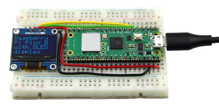
After Successfully uploading the code, you should see the text "Raspberry Pi Pico W" with "with OLED display" displayed on the OLED screen.
Hope you enjoyed the article and learned something useful from it. If you have any questions, you can leave them in the comment section below.
#include <Adafruit_SSD1306.h>
#include <Adafruit_GFX.h>
Adafruit_SSD1306 display(128, 64);
void setup() {
// Initialize the display
display.begin(SSD1306_SWITCHCAPVCC, 0x3C); // Address 0x3C for 128x32
// Clear the display
display.clearDisplay();
display.setTextColor(WHITE);
display.setTextSize(2);
display.setCursor(0, 0);
display.println("Raspberry Pi Pico W");
display.println("with OLED display");
display.display();
}
void loop() {
// Nothing to do here, just display the static text
}


