


Nowadays, the COVID-19 or the Novel coronavirus has emerged as a global pandemic and has affected more than 200 countries in the world. Hence, the public must get regular updates regarding the crisis, so that they can be informed about the number of infected cases and recoveries in any particular region. So here we will make a device, which can display Live Corona updates on the P10 DMD LED Matrix display using an Arduino and ESP32.
Components used
- ESP32 Wi-Fi Module
- Arduino Nano
- Logic converter (5 to 3.3V)
- 32*16 P10 DMD Matrix display
- 16 Pin FRC connector-1
- 5V DC, 3 AMP SMPS
- Connectors
P10 LED Matrix Display Module
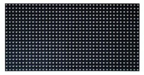
P10 is a 32*16 LED Matrix module which is popular for displaying big advertisements. There are 512 high-intensity LEDs in each unit of the P10 LED Module which consists, 32 LEDs in each row and 16 LEDs in each column.
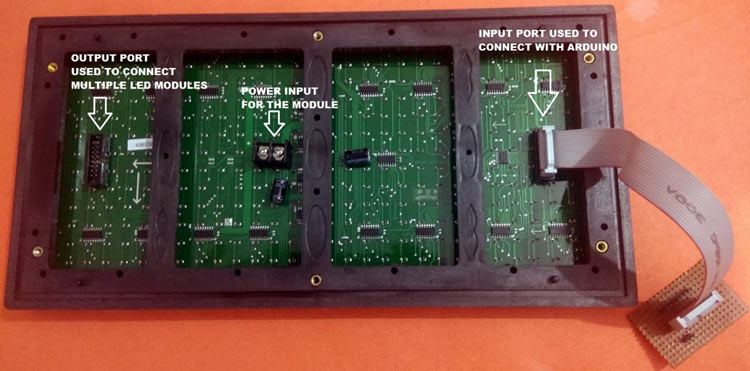
P10 LED modules can be multiplexed to build a bigger size display. There are two ports in a P10 module- input and output port. An input port is used for the incoming data from the Arduino side and the output port is used to connect the module to another LED P10 module.
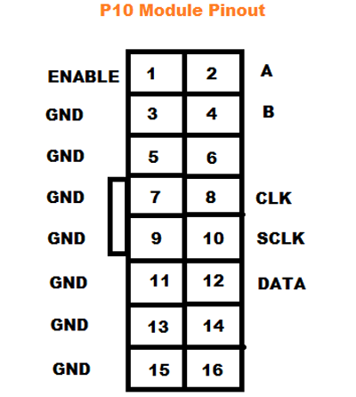
Pin Description of P10 LED Module:
- Enable: This pin is used to control the brightness of the LED panel, by giving a PWM pulse to it.
- A, B: These are called multiplex select pins. They take digital input to select any multiplex rows.
- Shift clock (CLK), Store clock (SCLK) and Data: These are the normal shift register control pins. Here a shift register 74HC595 is used.
COVID19 Live Data Tracker Circuit Diagram
![]()
Arduino UNO and P10 display module are connected for Corona Live data tracker as per the table below:
|
P10 LED Module |
Arduino UNO |
|
ENABLE |
D9 |
|
A |
D3 |
|
B |
D4 |
|
CLK |
D13 |
|
SCLK |
D8 |
|
DATA |
D11 |
|
GND |
GND |
![]()
Note: The P10 LED display module needs a separate DC power supply of 5V, 3A. If you connect more than one display, then increase the power supply of SMPS accordingly.
API for getting the COVID19 Live Data
Here we need to get the data from the internet using API and then send it to Arduino Nano via serial communication to display it on the P10 display. For that, an HTTP get request is made to read the JSON data available on the website. This API is provided by Coronavirus Disease GIS Hub and can be easily configured to get the query URL for displaying total Infected Cases and recovered cases for India. The country/Region can also be changed if you want to use this for a different country.
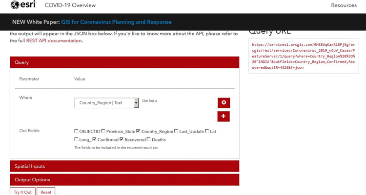
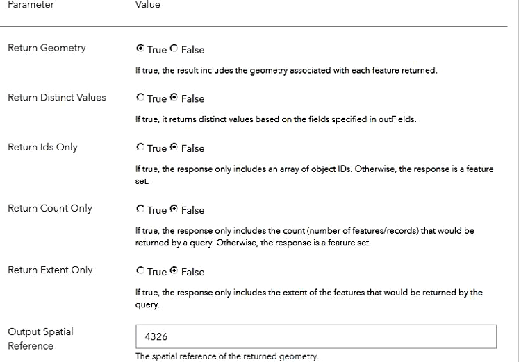
As shown in the figure above, visit the website given in the link above, and set the parameters as shown. For example, In the 'where' dropdown menu, set the country name, which is “India” in my case. You can set another country as per your requirements. Similarly in the output field checkbox, check the required output parameters, which are confirmed and recovered case in my case.
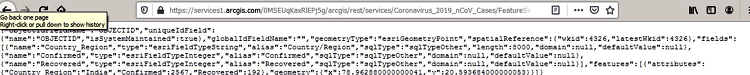
After setting all these parameters, click on the “Try it out” button. After this, in the top right corner, copy the “Query URL” contents and paste it in another tab of Browser where you will get an output screen as shown below:
After getting the JSON data, now generate the deserialization code, which we need to add in ESP32 programming. For that, go to the ArduinoJson Assistant and paste the JSON data in the Input section.
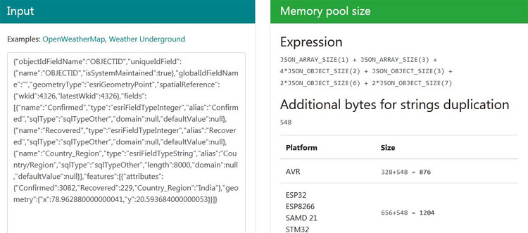
Now go to the parsing program and copy the code section that is required for your application. In my case, I used only confirmed and recovered cases in India.
![]()
Programming ESP32 for Covid19 Live Tracker
Here Arduino IDE is used to program ESP32. Complete code is given at the end of the program. Here we are explaining a few important parts of it. Also, to learn more about the ESP32 Wi-Fi module and how it can be used to build IoT projects, follow our ESP32 based IoT projects.
In the beginning, include all the required library files. HTTPClient library is used to get the data from the HTTP server. ArduinoJson library is used to phrase the data arrays.
#include <WiFi.h>
#include <HTTPClient.h>
#include <ArduinoJson.h>
Now, declare the network credentials- i.e. SSID and password. It is required to connect the ESP32 to the internet.
const char* ssid = "admin";
const char* password = "";
To connect ESP32 to the internet, call WiFi.begin and pass network SSID and password as its arguments. Check for the successful network connection using WiFi.status() and after a successful connection, print a message on Serial Monitor.
WiFi.begin(ssid, password);
  while (WiFi.status() != WL_CONNECTED)
  {
    delay(1000);
    Serial.println(".....");
  }
  Serial.println("Connected Successfully");
Now create a JSON object using the StaticJsonDocument class, using which we will send the serial parameter to Arduino Nano for display on P10 Module.
StaticJsonDocument<1000> root;
Now enter the API URL link using which we will get the total confirmed cases and Recovered cases in India. You can change the country name in the URL according to you.
http.begin(“https://services1.arcgis.co............................”);
Now inside the void loop() function, verify the received JSON file by the ESP32 by reading it and print JSON data on the serial monitor.
int httpCode = http.GET();
    if (httpCode > 0)
    {
      String payload = http.getString();
      Serial.println(payload);
Then, write the code, which we have already got from the ArduinoJson Assistant website. It is as follows:
      JsonObject features_0_attributes = doc["features"][0]["attributes"];
      const char* features_0_attributes_Country_Region = features_0_attributes["Country_Region"];
      int features_0_attributes_Confirmed = features_0_attributes["Confirmed"];
      int features_0_attributes_Recovered = features_0_attributes["Recovered"];
Finally, declare two JSON objects which will be sent to Arduino Nano, using serial communication. These can be done using serializeJson as shown below:
      root["Confirmed"] = features_0_attributes_Confirmed;
      root["Recovered"] = features_0_attributes_Recovered;
      serializeJson(root, Serial);
Programming of Arduino Nano
Now, write the code for the receiver section, where Arduino Nano is used for displaying the parameters on a P10 Matrix display. We previously interfaced Arduino Uno with a P10 LED display.
Start the code by including all the necessary library files to be used. Here TimerOne library is used for display scrolling Time properties and LedP10 library is used for the P10 Matrix display. ArduinoJson library is used to phrase the data arrays. Complete code is given at the end.
#include <TimerOne.h>
#include"SPI.h"
#include <ledP10.h>
#include <ArduinoJson.h>
Then, define the Arduino pins which are connected to the P10 display.
myled.init(3, 4, 8, 9,1);
Inside loop(), create a JSON object using the StaticJsonDocument class, using which we will receive the serial parameter from ESP32 for display on P10 Module.
StaticJsonDocument<1000> root;
Now deserialize the received JSON data, and assign them to individual variables, which will be displayed on the P10 display.
  deserializeJson(root, Serial);
  data1 = root["Confirmed"];
  data2 = root["Recovered"];
Now a function show1() is defined, where the string is declared and two variables are passed (in my case no. of confirmed cases and no. of recovered cases). Then it is converted to constant char array using toCharArray and then it is displayed on P10 display using function showmsg_single_scroll.
void show1(int x,int y)
{
  String data="Total cases: "+String(x)+" * Total Recovered: "+String(y)+" * Stay Home Stay Safe * ";
  int str_len = data.length() + 1;
  char buf[str_len];
  data.toCharArray(buf, str_len);
  myled.showmsg_single_scroll(buf,1,3,0);
  delay(1000);
}
![]()
This is how a P10 LED display can be used to show live data updates on Corona cases in any particular region or the whole world.
#include <WiFi.h>
#include <HTTPClient.h>
#include <ArduinoJson.h>
const char* ssid = "admin";
const char* password = "";
void setup()
{
Serial.begin(115200);
WiFi.begin(ssid, password);
while (WiFi.status() != WL_CONNECTED)
{
delay(1000);
Serial.println(".....");
}
Serial.println("Connected Successfully");
}
StaticJsonDocument<1000> root;
void loop()
{
if (WiFi.status() == WL_CONNECTED)
{
HTTPClient http;
http.begin("https://services1.arcgis.com/0MSEUqKaxRlEPj5g/arcgis/rest/services/Coronavirus_2019_nCoV_Cases/FeatureServer/1/query?where=UPPER(Country_Region)%20like%20%27%25INDIA%25%27&outFields=Country_Region,Confirmed,Recovered&returnGeometry=false&outSR=4326&f=json");
int httpCode = http.GET();
if (httpCode > 0)
{
String payload = http.getString();
Serial.println(payload);
const size_t capacity = JSON_ARRAY_SIZE(1) + JSON_ARRAY_SIZE(3) + JSON_OBJECT_SIZE(1) + 2 * JSON_OBJECT_SIZE(2) + JSON_OBJECT_SIZE(3) + 2 * JSON_OBJECT_SIZE(6) + 2 * JSON_OBJECT_SIZE(7) + 600;
DynamicJsonDocument doc(capacity);
deserializeJson(doc, payload);
JsonObject features_0_attributes = doc["features"][0]["attributes"];
const char* features_0_attributes_Country_Region = features_0_attributes["Country_Region"]; // "India"
int features_0_attributes_Confirmed = features_0_attributes["Confirmed"];
int features_0_attributes_Recovered = features_0_attributes["Recovered"];
root["Confirmed"] = features_0_attributes_Confirmed;
root["Recovered"] = features_0_attributes_Recovered;
serializeJson(root, Serial);
}
http.end();
}
}
#include <TimerOne.h>
#include"SPI.h"
#include <ledP10.h>
#include <ArduinoJson.h>
LedP10 myled;
int data1, data2;
void setup()
{
myled.init(3, 4, 8, 9,1);
Serial.begin(115200);
}
void loop()
{
StaticJsonDocument<1000> root;
deserializeJson(root, Serial);
data1 = root["Confirmed"];
data2 = root["Recovered"];
if(data1!=0 && data2!=0)
{
show1(data1,data2);
}
}
void show1(int x,int y)
{
String data="Total cases: "+String(x)+" * Total Recovered: "+String(y)+" * Stay Home Stay Safe * ";
int str_len = data.length() + 1;
char buf[str_len];
data.toCharArray(buf, str_len);
myled.showmsg_single_scroll(buf,1,3,0);
delay(1000);
}


