


The ESP32-CAM based CCTV camera is a project that allows you to create a remote surveillance camera using the ESP32-CAM module and the VLC player. The ESP32-CAM board is a popular combination of the ESP32 microcontroller and a camera module OV2640, making it suitable for capturing images and streaming video. The project introduces the ESP32 CAM module which is a small yet powerful camera module equipped with ESP32 microcontroller and leveraged with Wi-Fi capabilities, making the project cost-effective & easily affordable.
In this project, our CAM module seamlessly integrates with a Wi-Fi network to transfer the live stream visuals over to the wireless communication, received by devices connected with the same WiFi. Users can wirelessly watch the live stream through the VLC streaming platform which uses the real-time monitoring camera feed.
Throughout this project, we will learn about the setup process, connection diagram, and demonstration to code the ESP32CAM to capture video and showcase the steps to initiate the VLC stream.
Check out all Previously created Surveillance & streaming projects using ESP32-CAM: ESP32 CAM Based Surveillance Robot using Arduino IDE
Components Required
- ESP32 CAM Module
- USB to UART TTL Serial converter/ FTDI module
- Connecting Wires
- External 5v power Supply
ESP32 CAM Module
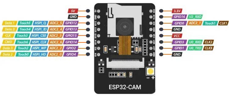
The ESP32-CAM module (developed by AI-Thinker) uses an ESP32 microcontroller with an OV2640 camera sensor which comes with support for Wi-Fi and Bluetooth connectivity, some of the key specifications are:
- Microcontroller: ESP32-D0WDQ6, dual-core 32-bit, up to 240 MHz clock speed.
- Camera: OV2640, 2MP resolution (1600x1200 pixels).
- Memory: 4 MB Flash, approximately 520-600 KB RAM, and external 8MB PSRAM.
- Supports SD card reader up to 4GB.
- The ESP32-S chip offers a total of 32 GPIO pins; however, since a significant number of them are reserved for internal use, the ESP32-CAM module offers only 10 available GPIO pins. Despite this limitation, these pins are versatile and are used for interfacing UART, SPI, I2C, PWM, ADC, DAC, and Touch functionalities, making the ESP32-CAM a powerful and flexible platform for various applications.
- Power Pins include 5v & 3.3v. It has an inbuilt 3.3 voltage regulator.
FTDI Module
Since the ESP32 CAM board does not have a USB to TTL serial converter IC. Hence the only option left behind is to use the FTDI module to program the ESP32 board using a PC. The below diagram gives you an idea about its pinout & its interfaces.
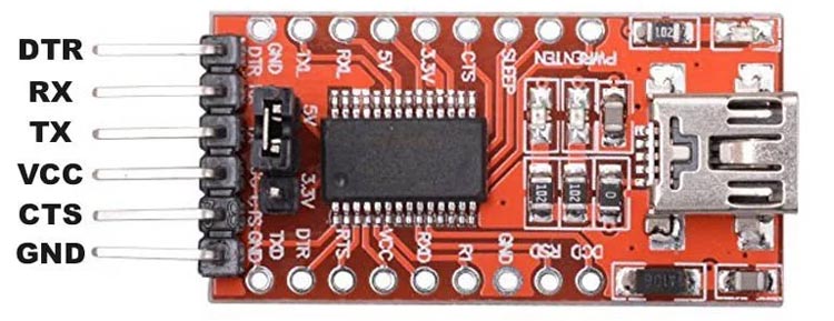
Generally, the module has Six pins to communicate with the microcontrollers.
GND: Ground pin
5V: Output for 5V version, input for 3.3V version
TXD: Transmit Data (Output from module)
RXD: Receive Data (Input to the module)
CTS: Clear to Send (Input to the module)
DTR: Data Terminal Ready (Output from module)
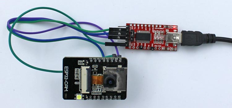
ESP32 CAM and FTDI Programmer Circuit Diagram
The Serial Communication Technique is used to program the ESP32 Cam using FTDI (USB-to-UART) module. The FTDI module acts as a serial converter between the computer's USB to the UART interface for the ESP-32 CAM, allowing you to upload code and interact with the module.
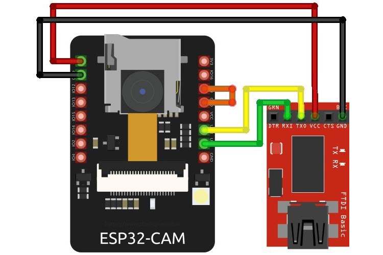
By following the connection diagram, you can connect the ESP32-CAM with an FTDI module for programming:
- Connect GND on the FTDI module to GND on the ESP32-CAM.
- Connect RX on the FTDI module to U0TXD on the ESP32-CAM.
- Connect TX on the FTDI module to U0RXD on the ESP32-CAM.
- Connect VCC on the FTDI module to the 5V power pin on the ESP32-CAM.
Important: Sort the GPIO0 to GND of the ESP32-CAM to put the board in boot mode for programming. Later On, necessarily needs to remove the sorting after the successful uploading of the program.
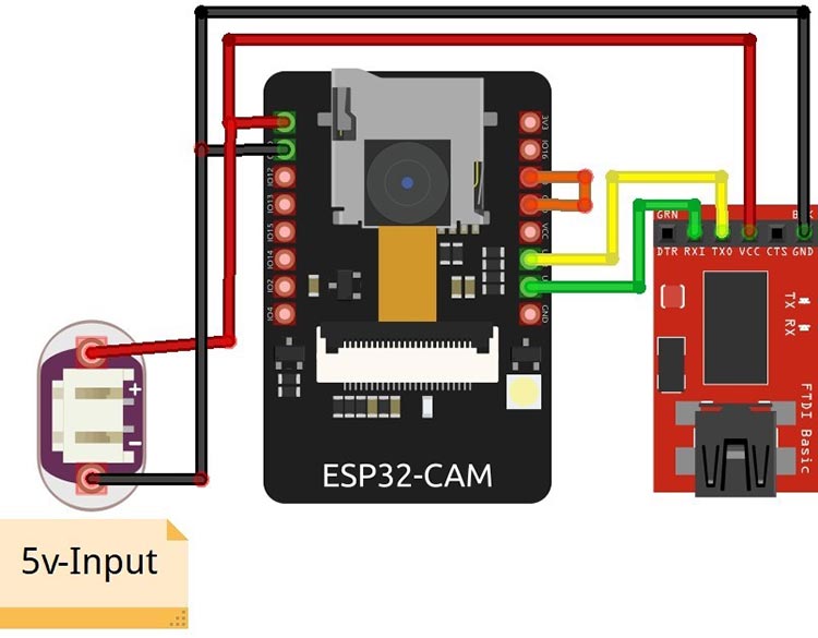
In certain ESP32-CAM boards, you may encounter a brown-out detector error, which is typically caused by an insufficient power supply from the FTDI (USB to UART) module. To address this issue, it is recommended to connect an external 5V power supply directly to the ESP32-CAM board. This external power supply will ensure the ESP32-CAM receives adequate voltage and can operate without triggering the brown-out detector error as shown below diagram:
Arduino Code for Programming ESP32-CAM CCTV Camera
We will use Arduino IDE to program our development board. The program sets the various interfacing pins for the camera module and created a web-based streaming link that will be used to stream on VLC. For that, we need to download the code sketch. You can find the complete code from the GitHub.
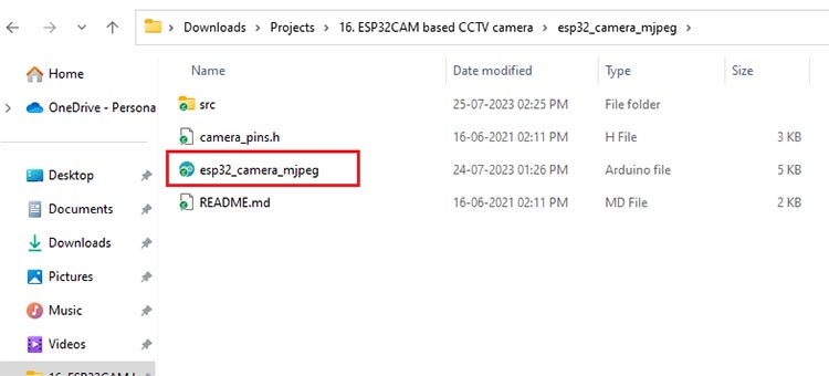
Download the complete code in a zip file, then unzip the folder & extract it. After opening the folder, you will find an ino file named esp32_camera_mjpeg, our code sketch file.
Open the sketch file in Arduino IDE. Since this is the Raw code and due to that, we have to do some modifications in the code as per our environment. Let’s take a look:
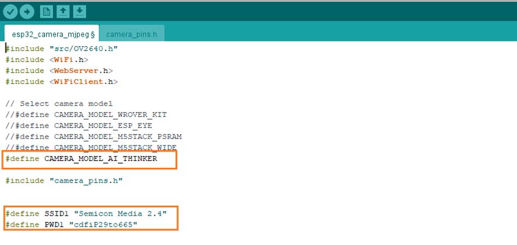
At the start of the code, you will find the definition given for the particular camera model hardware. By default, there will be CAMERA_MODEL_ESP_EYE selected but our module uses CAMERA_MODEL_AI_THINKER. So, comment on the previously selected and Uncomment the CAMERA_MODEL_AI_THINKER model.
// Select the camera model
//#define CAMERA_MODEL_WROVER_KIT
//#define CAMERA_MODEL_ESP_EYE
//#define CAMERA_MODEL_M5STACK_PSRAM
//#define CAMERA_MODEL_M5STACK_WIDE
#define CAMERA_MODEL_AI_THINKER
Specify the correct Network credentials including SSID and Password to successfully connect to an encrypted network. Ensure your network has 2.4 GHz bandwidth, making it compatible with the development board.
#define SSID1 "SSID-Name"
#define PWD1 "password"
The image quality and frame size of OV2640 can be adjusted via the below section of the code.
- FRAMESIZE_UXGA (1600 x 1200)
- FRAMESIZE_QVGA (320 x 240)
The value of jpeg_quality can range from 0 to 63, with lower numbers representing higher image quality. However, setting a very low number for jpeg_quality, especially at higher resolutions, may lead to issues such as image corruption, strange colors, or even crashing of the ESP32-CAM.
To avoid such problems, finding a balance between image quality and memory constraints is essential. If you notice that the images taken with the ESP32-CAM are cut in half, contain strange colors, or the module is experiencing crashes, consider increasing the jpeg_quality value to improve the image output and stability.
// Frame parameters
  config.frame_size = FRAMESIZE_UXGA;
  //config.frame_size = FRAMESIZE_QVGA;
  config.jpeg_quality = 12;
  config.fb_count = 2;
Now that the code has done with all the necessary changes, it is time to proceed with compiling and uploading the code.
Before uploading your code to the ESP32-CAM board, select the correct board and COM port. To do this, follow these steps:
- Go to "Tools" in the Arduino IDE menu.
- Click on "Board", then “ESP32 Arduino”, and select "AI Thinker ESP32-CAM" from the list of available boards.
Note: If you haven’t found “ESP32 Arduino” in boards, it means the board isn’t installed in your IDE. Here is the previous tutorial to give you insight into installing the ESP32 board.

Additionally, ensure that the FTDI programmer is correctly connected to the module. Also, make sure that GPIO0 is grounded as well. This grounding of GPIO0 is essential to put the ESP32-CAM into programming mode.
Once all these are done, you can proceed with the compilation and uploading process after selecting the correct board and COM port.
Monitoring the Live Streaming on the Web Interface
Once the uploading process is completed, unplug the board from the PC. Remove the IO0 & GND jumper connection from the ESP32-CAM board then plug it again into the PC. Open the Serial monitor and press the reset button on the board. By doing this, the ESP32-CAM module will attempt to connect to the configured WiFi network.
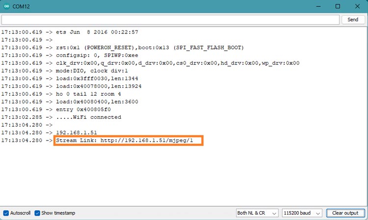
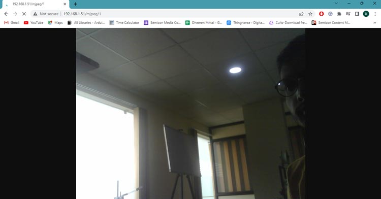
A MPEG link will display on the serial monitor. Copy the link and Search in any browser. You will find that the live streaming will get started.
Configuring the Live Streaming on VLC
Let's now stream the live video on the VLC media app. Many of you may have already used a VLC media player on Android or Windows. We are using this versatile player for streaming, which promises to be a fun, creative, and practical implementation. If you haven't installed the player yet, you can easily download it from the Play Store for Android or by using any web browser for Windows.
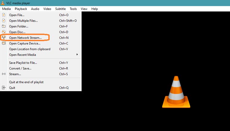
- Open the VLC media player on your device (Android, Windows, or any other platform).
- In VLC, go to "Media" in the menu and select "Open Network Stream."
- In the "Network" tab, enter the URL for the live video stream. The URL should be the same as displayed on a serial monitor or used for web streaming.
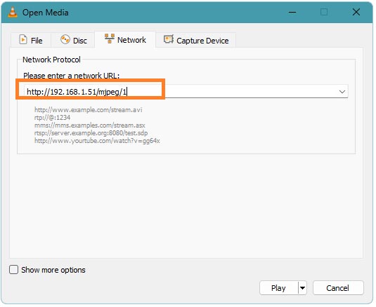
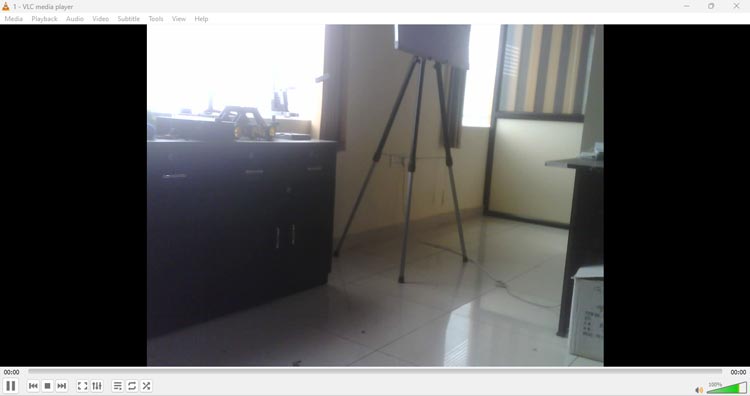
- Click on “Play” to start the live stream.
Note: Make sure the Live streaming device is connected to the same network as your ESP32-CAM Board.
Hope you liked and enjoyed the project and learned something useful from it. If you have any questions, you can leave them in the comment section below.
/*
This is a simple MJPEG streaming webserver implemented for AI-Thinker ESP32-CAM and
ESP32-EYE modules.
This is tested to work with VLC and Blynk video widget.
Inspired by and based on this Instructable: $9 RTSP Video Streamer Using the ESP32-CAM Board
(https://www.instructables.com/id/9-RTSP-Video-Streamer-Using-the-ESP32-CAM-Board/)
Board: AI-Thinker ESP32-CAM
*/
#include "src/OV2640.h"
#include <WiFi.h>
#include <WebServer.h>
#include <WiFiClient.h>
// Select camera model
//#define CAMERA_MODEL_WROVER_KIT
//#define CAMERA_MODEL_ESP_EYE
//#define CAMERA_MODEL_M5STACK_PSRAM
//#define CAMERA_MODEL_M5STACK_WIDE
#define CAMERA_MODEL_AI_THINKER
#include "camera_pins.h"
#define SSID1 "Semicon Media 2.4"
#define PWD1 "cdfiP29to665"
OV2640 cam;
WebServer server(80);
const char HEADER[] = "HTTP/1.1 200 OK\r\n" \
"Access-Control-Allow-Origin: *\r\n" \
"Content-Type: multipart/x-mixed-replace; boundary=123456789000000000000987654321\r\n";
const char BOUNDARY[] = "\r\n--123456789000000000000987654321\r\n";
const char CTNTTYPE[] = "Content-Type: image/jpeg\r\nContent-Length: ";
const int hdrLen = strlen(HEADER);
const int bdrLen = strlen(BOUNDARY);
const int cntLen = strlen(CTNTTYPE);
void handle_jpg_stream(void)
{
char buf[32];
int s;
WiFiClient client = server.client();
client.write(HEADER, hdrLen);
client.write(BOUNDARY, bdrLen);
while (true)
{
if (!client.connected()) break;
cam.run();
s = cam.getSize();
client.write(CTNTTYPE, cntLen);
sprintf( buf, "%d\r\n\r\n", s );
client.write(buf, strlen(buf));
client.write((char *)cam.getfb(), s);
client.write(BOUNDARY, bdrLen);
}
}
const char JHEADER[] = "HTTP/1.1 200 OK\r\n" \
"Content-disposition: inline; filename=capture.jpg\r\n" \
"Content-type: image/jpeg\r\n\r\n";
const int jhdLen = strlen(JHEADER);
void handle_jpg(void)
{
WiFiClient client = server.client();
cam.run();
if (!client.connected()) return;
client.write(JHEADER, jhdLen);
client.write((char *)cam.getfb(), cam.getSize());
}
void handleNotFound()
{
String message = "Server is running!\n\n";
message += "URI: ";
message += server.uri();
message += "\nMethod: ";
message += (server.method() == HTTP_GET) ? "GET" : "POST";
message += "\nArguments: ";
message += server.args();
message += "\n";
server.send(200, "text / plain", message);
}
void setup()
{
Serial.begin(115200);
//while (!Serial); //wait for serial connection.
camera_config_t config;
config.ledc_channel = LEDC_CHANNEL_0;
config.ledc_timer = LEDC_TIMER_0;
config.pin_d0 = Y2_GPIO_NUM;
config.pin_d1 = Y3_GPIO_NUM;
config.pin_d2 = Y4_GPIO_NUM;
config.pin_d3 = Y5_GPIO_NUM;
config.pin_d4 = Y6_GPIO_NUM;
config.pin_d5 = Y7_GPIO_NUM;
config.pin_d6 = Y8_GPIO_NUM;
config.pin_d7 = Y9_GPIO_NUM;
config.pin_xclk = XCLK_GPIO_NUM;
config.pin_pclk = PCLK_GPIO_NUM;
config.pin_vsync = VSYNC_GPIO_NUM;
config.pin_href = HREF_GPIO_NUM;
config.pin_sscb_sda = SIOD_GPIO_NUM;
config.pin_sscb_scl = SIOC_GPIO_NUM;
config.pin_pwdn = PWDN_GPIO_NUM;
config.pin_reset = RESET_GPIO_NUM;
config.xclk_freq_hz = 20000000;
config.pixel_format = PIXFORMAT_JPEG;
// Frame parameters
config.frame_size = FRAMESIZE_UXGA;
//config.frame_size = FRAMESIZE_QVGA;
config.jpeg_quality = 12;
config.fb_count = 2;
#if defined(CAMERA_MODEL_ESP_EYE)
pinMode(13, INPUT_PULLUP);
pinMode(14, INPUT_PULLUP);
#endif
cam.init(config);
IPAddress ip;
WiFi.mode(WIFI_STA);
WiFi.begin(SSID1, PWD1);
while (WiFi.status() != WL_CONNECTED)
{
delay(500);
Serial.print(F("."));
}
ip = WiFi.localIP();
Serial.println(F("WiFi connected"));
Serial.println("");
Serial.println(ip);
Serial.print("Stream Link: http://");
Serial.print(ip);
Serial.println("/mjpeg/1");
server.on("/mjpeg/1", HTTP_GET, handle_jpg_stream);
server.on("/jpg", HTTP_GET, handle_jpg);
server.onNotFound(handleNotFound);
server.begin();
}
void loop()
{
server.handleClient();
}


