


Traditional key based door locks are now slowly going out of the trend and electronically controlled door locks are getting popular in the market with increasing IoT based environment. People are now building IoT controlled home which not only gives easiness to control the devices but also add more security to your home. There are many IoT controlled locks are available like Web controlled Door Lock, Face Recognition Door Lock, etc.
In this project, we are going to build a Biometric Lock using Arduino Nano with Bluetooth Module, Solenoid Lock, and Android Phone. Apart from hardware, a mobile application is also used to scan and verify the fingerprint and send the confirmation ID to Arduino through Bluetooth. Here we will use Smart Phone Finger Print Sensor to lock and unlock the door lock.
Components Required
- Arduino Nano
- Bluetooth Module (HC05)
- Relay Module
- Solenoid Lock
- Buzzer
- LED
- Jumper Wires
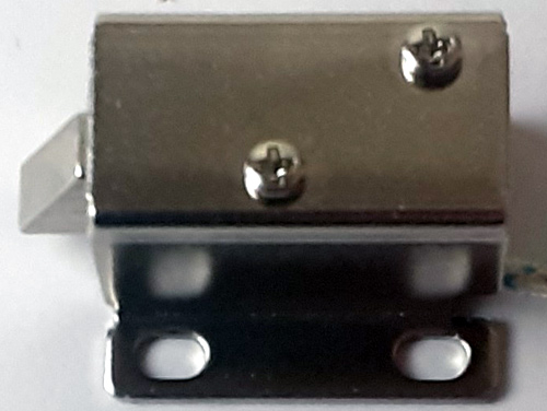
Solenoid Lock
In a conventional door lock, there is a key to pull or push the latch, and we have to operate it manually, but in a solenoid lock, the latch can be operated automatically by applying a voltage. Solenoid lock has a low-voltage solenoid that pulls the latch back into the door when an interrupt (Pushbutton, Relay, etc.) is activated. The latch will retain its position until the interrupt is enabled. The operating voltage for the solenoid lock is 12V. You can also use 9V, but it results in slower operation. Solenoid door locks are mainly used in remote areas to automate operations without involving any human effort.
Circuit Diagram
The circuit diagram for Fingerprint Door Lock using Arduino is given below:
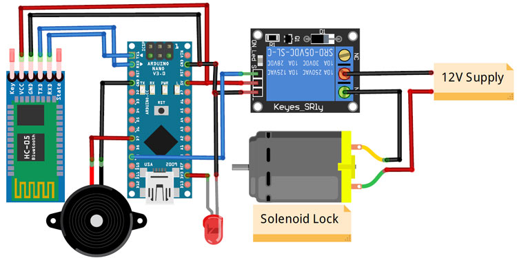
Connections for this project are very simple. Here we are only connecting a solenoid lock, relay module, and a Bluetooth module with Arduino Nano. The input pin of the relay is connected to the pin 9 of Arduino Nano while VCC and Ground pins are connected to 5V and GND pin of Nano. 5V and GND pins of the Bluetooth module are connected to 5V and GND of Nano while Tx and Rx pins are connected to Rx and Tx of Nano respectively. The positive pin of the buzzer is connected to pin 7 of Arduino and the negative pin is connected to GND of Arduino.
Bluetooth is a very useful wireless communication medium to build IoT projects, we previously used Bluetooth to build many IoT projects.
Code Explanation
The complete code for Fingerprint Lock using Arduino is given at the end of the page. The stepwise description of the code is given below.
The Arduino Nano and Bluetooth module communicate via serial communication and this makes the code very simple. Since we are using the Arduino’s hardware serial pins (Rx & Tx) and not software serial, we don’t need to include a library for Serial Communication.
The basic function of the code is to monitor the incoming serial data and compare it with pre-defined conditions, if the fingerprint is authorized then open the lock else keep it locked.
So start the code by declaring a variable to hold the data received from the Bluetooth and define the Arduino pins to which the Relay and buzzer are connected.
int value1;
#define relay 9
const int buzzer = 7;
Inside the setup() function, start the serial communication with a baud rate of 9600 and also set the pinMode for the Relay and buzzer pins.
void setup()
 {
  Serial.begin(9600);
  pinMode(relay, OUTPUT);
  pinMode(buzzer, OUTPUT);
  digitalWrite(relay, LOW);
Next, inside the loop() function, check for the availability of data from the Bluetooth module, if the data is available, then read the data and store it in a variable. After that, use an if statement to compare it and see if it is a 1 or 0. If the data is 1, then open the lock, and if it’s 0, then keep it locked.
void loop()
 {
  while(Serial.available()==0);
  value1 = Serial.read();
  Serial.print(value1);
  if (value1==1)
  {
    Serial.print("Unlocking");
    digitalWrite(relay, LOW);
  }
  if (value1==0)
  {
   digitalWrite(relay, HIGH);
   Serial.print("Locking");
  }
}
Android App for Arduino based Fingerprint Door Lock
The app for this project was designed using the Kodular app inventor. Creating an app using Kodular is very simple; you can make an app by combining the blocks according to the flow chart of your project.
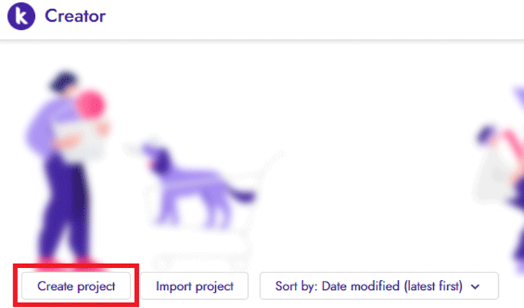
To create an app with Kodular, navigate to Kodular.io and create an account if you don’t have one, Login to your account, and then click on the ‘Create Apps’ option.

After that, you will be taken to the Projects screen. Click on the ‘Create Project’ button to create a Project.
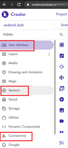
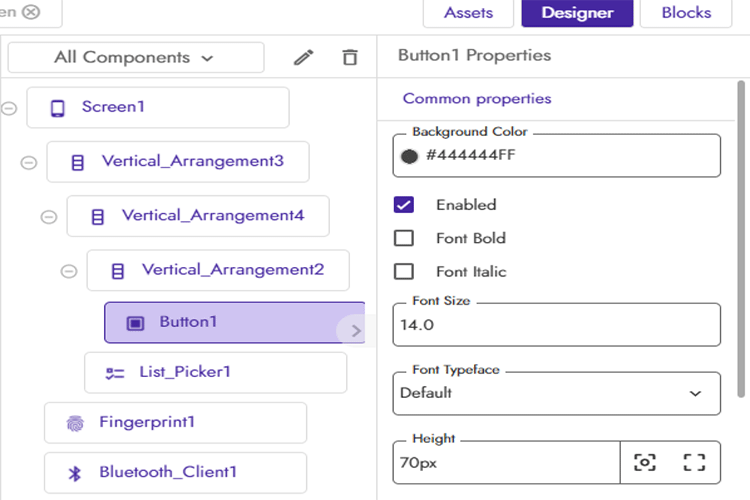
Name the app and click ‘Finish’. The project will be created and you will be taken to the Designer page of the project. Now on the Designer page, add these four components from Components Palette to create a layout for the app: Bluetooth Client, Fingerprint, List Picker, and Image Button. List picker and Button can be found in ‘User Interface’ while Fingerprint and Bluetooth can be picked from ‘Sensors’ & ‘Connectivity’.
Screen properties can be changed by changing the properties for each block.
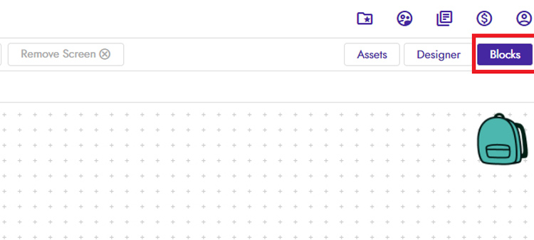
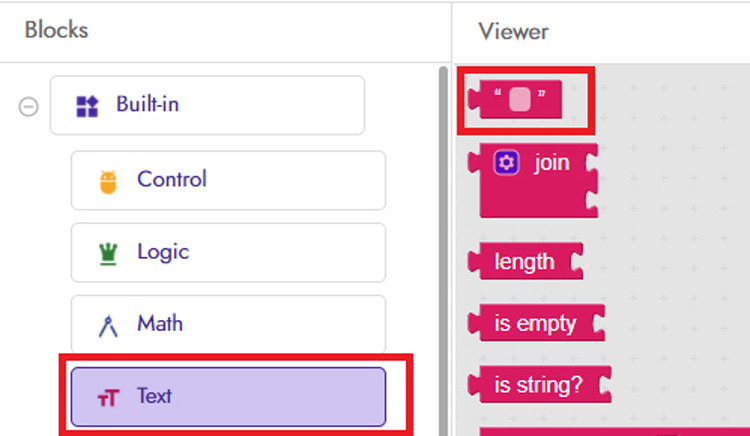
After that, move to the ‘Blocks’ screen to build the app using the blocks.
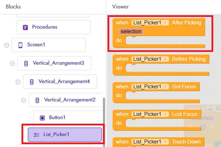
Now scroll down, click on the ‘List_Picker1’ and drag & drop the first code block as shown in the image:
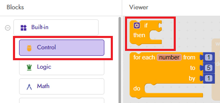
In the next step, click on the ‘Control’ block and then drag & drop the first code block on the Viewer screen.
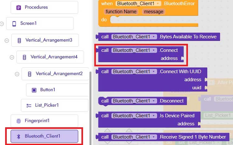
After that, go to the ‘Bluetooth_client1’ block and select the ‘Bluetooth_client.connect’ code block.
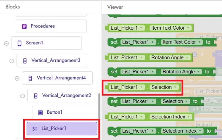
Then go to the ‘List_Picker’ block and select the ‘Selection code block’ as shown in the below image.
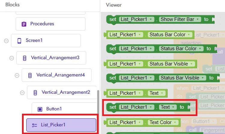
Now in the next step, again go to ‘List_Picker’ block and select the ‘List_Picker. Text to’ code block as shown in the below image.
After that, go to the ‘Text’ block and select the first code block.
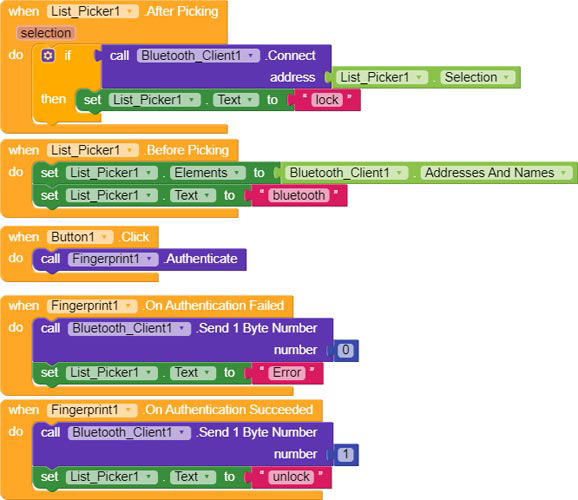
With this, the first code block is finished. We need to create three more code blocks to call the fingerprint sensor of the Android phone and authenticate the fingerprint. The complete code block is shown in the below picture. Use this picture to join the rest of the code blocks.
When all the blocks are connected, export the .apk file on your laptop or you can directly export the apk to your phone using the QR Code.
The .aia and .apk file of this app can be downloaded from here.
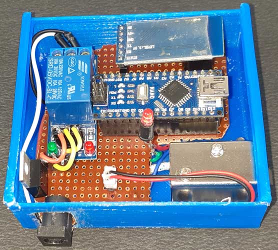
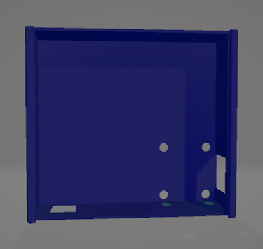
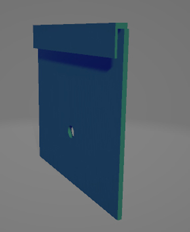
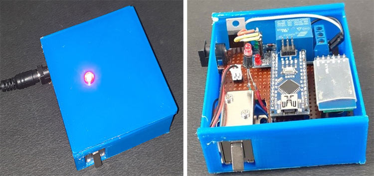
3D Printed Casing for Biometric Lock
Here I designed a 3D printed casing for this Biometric Lock. For that, I measured the dimensions of the Perfboard and LED hole. The design looked something like this below once it was done.
After that, I exported it as an STL file, sliced it based on printer settings, and finally printed it. The STL file is available for download from Thingiverse and you can print your own casing using it.
After printing the case, assemble the circuit into the casing and it looks something like below.
Testing the Fingerprint Door Lock using Arduino Project
After installing the .apk and connecting the hardware as per the circuit diagram, connect the Arduino to the laptop and upload the code (Remove the TX & Rx pins before uploading the code). After that, turn on the Bluetooth of your phone and then pair the Bluetooth module with your phone.
Now open the app and click on the Bluetooth icon, and connect with the Bluetooth module.
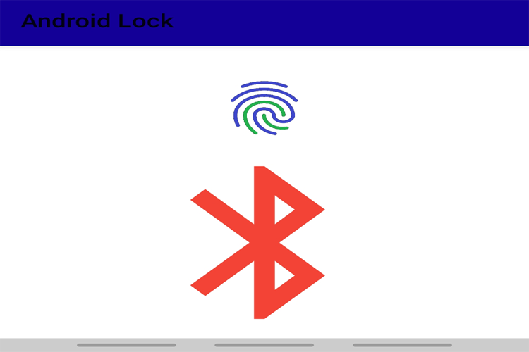
Once the Bluetooth module connects with the app, the Bluetooth icon changes into Lock Icon.
After that, touch the fingerprint button and it will ask you to scan your finger on the fingerprint sensor. If the fingerprint is authentic, then it will open the door else the door will remain in a locked position.
This is how you can use your smart phone’s fingerprint sensor to control a door lock. A working video and complete code are given below.
int value1;
#define relay 9
const int buzzer = 7;
void setup()
{
Serial.begin(9600);
pinMode(relay, OUTPUT);
pinMode(buzzer, OUTPUT);
digitalWrite(relay, LOW);
}
void loop()
{
Serial.print("Reading");
while(Serial.available()==0);
value1 = Serial.read();
Serial.print(value1);
if (value1==1)
{
Serial.print("Unlocking");
digitalWrite(relay, LOW);
digitalWrite(buzzer, HIGH);
delay(1000);
digitalWrite(buzzer, LOW);
}
if (value1==0)
{
digitalWrite(relay, HIGH);
Serial.print("Locking");
}
}


