


Every Marvel fan would have envied of having his/her personal assistant like JARVIS to get things done on their voice command. But, we are far from something as smart as that, and the closest thing that we have today are voice assistants like Google Assistant, Siri, Cortana, etc. Today we have dozens of IoT based smart devices in the market that can be controlled using these voice assistants, but it is not fair to go on and replace every electronic device in our home to make it suitable for home automation. This is why, in this project, we will be building a Universal IR Remote that can control every electronic device that operates in an IR Remote. Basically, we will be duplicating the original Remote signals with a NodeMCU so that we can trigger these signals from the internet whenever required. The circuit in this project will concentrate specifically on building Universal AC Remote to turn any AC ON/OFF, but the procedure for other appliance are also very similar.
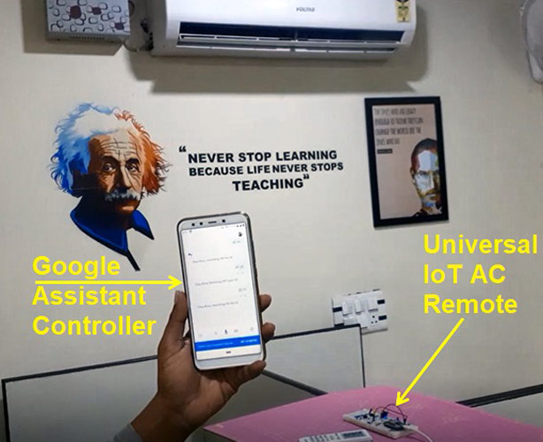
This IoT based Universal remote will operate on two steps, in the first step, it allows the user to feed in their original IR signal from their AC remote and then it allows the user to duplicate those signals whenever required through a voice command on Google assistant. To capture these commands from the remote, we are going to use a TOP1738 IC, which is an IR receiver. To send those signals through IR, we are using IR blaster, which is an IR LED.
Components Required
- NodeMCU
- TSOP1738 – IR receiver
- IR Blaster
- Push Buttons
- LEDs
- Resistors
- Connecting Wires
IR Signal Transmitter
The IR remote operates by modulating (Switching ON and OFF) the IR blaster (IR LED). When you see an IR LED in the remote glowing (using a camera that doesn't have an IR filter), it means that the LED is switching ON and OFF thousands of times per second. It is impossible to follow the LED switching on and off with our naked eyes. The frequency at which the IR LED is switching ON and OFF is called the carrier frequency. The data is placed on the carrier and sent using different modulation techniques. An example of a modulation technique is PWM. In this modulation, the ON and OFF durations of an IR LED is varied. These modulated signals are received by the IR receiver and decoded using an MCU.
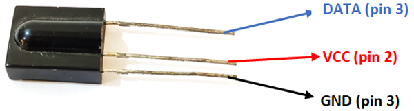
TSOP1738 (IR receiver)
TSOP1738 is like a sensor, which is sensitive to IR signals. So, we can use the TSOP1738 as an IR receiver. The sensor’s operating voltage is 5V and consumes 5mA. The TSOP1738 IC has 3 pins in which the center pin (pin 2) is VCC, and the pin closer to the center pin is a ground pin (pin 1). The remaining pin (pin 3) is the signal pin and is connected to the microcontroller to decode the received signals. The IC’s pinout is shown below.
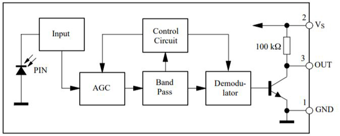
The ICs contain photodetector and the preamplifier in a single package with an internal filter for PCM frequency. The internal block diagram of the IC is shown below.
Keep in mind that the TSOP-1738 will receive only 38Khz IR signals, and is compatible with our project as all the remotes in India work on 38KhZ. Kindly ensure if it is the same in your country, and if it is not, then change the IC accordingly.
Encoding and Decoding of IR Signals
Decoding TV remote is an easy task as most of the time they send only one value. When it comes to AC remotes, they send several parameters at the same time. Along with these, each AC has a different protocol, which depends on the manufacturer. The communication between remote and the device which has a receiver follows different protocols like SONY, NEC, etc. The data is converted into Pronto Hex format depending on the protocol that the manufacturer chooses and then defines their code according to it.
IR Signal Decoding using NodeMCU
We are going to design our code in such a way that the user has to first capture the signals for each instruction (in this project, we are going to deal with switching on and switching off of the AC ) from the remote in raw data and then by mimicking the captured data, we will be controlling the AC through google assistant, which is present in the phone. To decode the incoming IR signals in raw data using NodeMCU, we will have to download the following library
Download ESP8266 IR Remote Library
After downloading the file, there is a small edit that you have to perform on the library files to execute our code. Open the src folder, find IRutils.CPP file. Open that file in the note pad and look for the code that is written in the function name called resultToHumanReadableBasic. Copy-paste the code given below in place of that code.
String resultToHumanReadableBasic(const decode_results * const results) {
  String output = "";
  // Reserve some space for the string to reduce heap fragmentation.
  output.reserve(2 * kStateSizeMax + 50);  // Should cover most cases.
  // Show Encoding standard
 // output += kProtocolStr + F("  : ");
  output += typeToString(results->decode_type, results->repeat);
  output += '\n';
  // Show Code & length
  //output += kCodeStr + F("      : ");
  //output += resultToHexidecimal(results);
  //output += kSpaceLBraceStr;
  //output += uint64ToString(results->bits);
  //output += ' ' + kBitsStr + F(")\n");
  return output;
}
Now, look for the code with the function name resultToSourceCode and paste the below code in place of that code. In the code given below, all we did is that we commented on the unnecessary commands which will be helpful in differentiating between the noise and data signal. More on this will be further explained in the Code explanation section.
String resultToSourceCode(const decode_results * const results) {
  String output = "";
  // Reserve some space for the string to reduce heap fragmentation.
  output.reserve(1536);  // 1.5KB should cover most cases.
  // Start declaration
  //output += F("uint16_t ");  // variable type
 // output += F("rawData[");   // array name
  output += uint64ToString(getCorrectedRawLength(results), 10);
  // array size
  Output += F(", ");  // Start declaration
  // Dump data
  for (uint16_t i = 1; i < results->rawlen; i++) {
    uint32_t usecs;
    for (usecs = results->rawbuf[i] * kRawTick; usecs > UINT16_MAX;
         usecs -= UINT16_MAX) {
      output += uint64ToString(UINT16_MAX);
      if (i % 2)
        output += F(", 0,  ");
      else
        output += F(",  0, ");
    }
    output += uint64ToString(usecs, 10);
    if (i < results->rawlen - 1)
      output += kCommaSpaceStr;            // ',' not needed on the last one
    if (i % 2 == 0) output += ' ';  // Extra if it was even.
  }
  // End declaration
  output += F("\n");
return output;
  // Comment
  output += F("  // ");
  output += typeToString(results->decode_type, results->repeat);
  // Only display the value if the decode type doesn't have an A/C state.
  if (!hasACState(results->decode_type))
    output += ' ' + uint64ToString(results->value, 16);
  output += F("\n");
  // Now dump "known" codes
  if (results->decode_type != UNKNOWN) {
    if (hasACState(results->decode_type)) {
#if DECODE_AC
      uint16_t nbytes = results->bits / 8;
      output += F("uint8_t state[");
      output += uint64ToString(nbytes);
      output += F("] = {");
      for (uint16_t i = 0; i < nbytes; i++) {
        output += F("0x");
        if (results->state[i] < 0x10) output += '0';
        output += uint64ToString(results->state[i], 16);
        if (i < nbytes - 1) output += kCommaSpaceStr;
      }
      output += F("};\n");
#endif  // DECODE_AC
    } else {
      // Simple protocols
      // Some protocols have an address &/or command.
      // NOTE: It will ignore the atypical case when a message has been
      // decoded but the address & the command are both 0.
      if (results->address > 0 || results->command > 0) {
        output += F("uint32_t address = 0x");
        output += uint64ToString(results->address, 16);
        output += F(";\n");
        output += F("uint32_t command = 0x");
        output += uint64ToString(results->command, 16);
        output += F(";\n");
      }
      // Most protocols have data
      output += F("uint64_t data = 0x");
      output += uint64ToString(results->value, 16);
      output += F(";\n");
    }
  }
  return output;
}
Voice Controlled AC Circuit Diagram
We are using a simple IR led as an IR blaster whose anode is connected to the D2 pin of the NodeMCU and the cathode terminal is connected to the GND. To indicate whether the push button is pressed or not, I have used LED for each button. In between the push button and the led, I have used a 100ohm resistor. The complete circuit diagram for IoT controlled AC Remote is shown below.
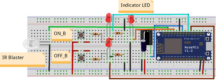
The cathode of the two LEDs is connected to the D7 and D8 pin of the NodeMCU. I have used 1Kohm resistors as a pull-down resistor for each pin of the NodeMCU. I have connected a green LED to the pin of D4 as an indicator to indicate various procedures in the program while running. The D5 pin of the NodeMCU is connected to tsop1738 IR receiver, the center pin is connected to the Vcc and the remaining pin is connected to the GND. A capacitor of 10uf is connected in parallel to the GND and VCC of the IR receiver to prevent noise. The module gets supply from the nodeMCU, which gets power from the USB cable.
Adafruit IO Setup for Voice-Controlled AC
This setup is regarding the communication between the android and NodeMCU. The Adafruit IO takes instruction from our phone through Google Assistant and then it communicates with the NodeMCU using IFTT. With Adafruit IO, your data can be uploaded, displayed, and monitored over the Internet, and you can make your own IoT projects. We have also built many other interesting Arafruit IO projects previously. To use Adafruit IO, the steps are as follows:
Step 1: The first thing you need to do is to sign up for Adafruit IO. Go to the https://io.adafruit.com and click on ‘Get Started for Free’ on the top right corner of the screen.

Step 2: A window will pop up in which you have to fill your details. After filling your details like name, mail id, username, etc. click on save settings, and your account is created.

Step 3: Now, you need to have your AIO key which is used in the coding. To get your AIO KEY, click on ‘AIO Key’, which is present at the top right side of the page.
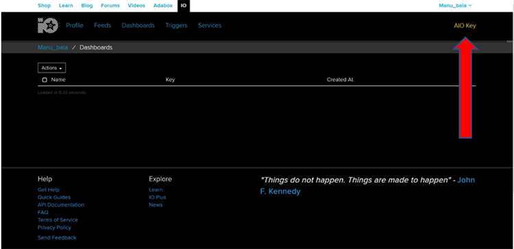
Step 4: A window will pop up with your AIO username and Active Key. Copy these as you will require in the next process.

Step 5: After getting your AIO key, you now have to create a New Feed. Select Feeds > view all. A new page will load, where you can see your past feeds. As you are new, you can only see Default.

Now, select Action > Create New Feed.
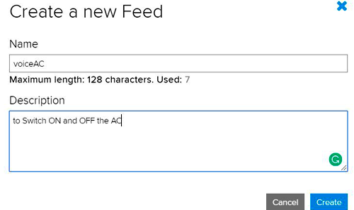
A window will pop up, asking you Name and Description. I named it VoiceAC and gave some description. After giving details, select ‘Create’ and done. With this, you have created your New Feed.
IFTTT Setup for Voice-controlled AC using Google Assistant
IFTTT (If This Then That) is a web-based service, which is used to create a conditional statement, called applets. Using IFTTT, we can create triggers for certain actions. For our project, we are going to create an applet that triggers, when we say a specific line using google assistant. First, we need to create an account on IFTT.
Note: Create an account on IFTTT using the same email ID which you used to create an account in Adafruit IO.
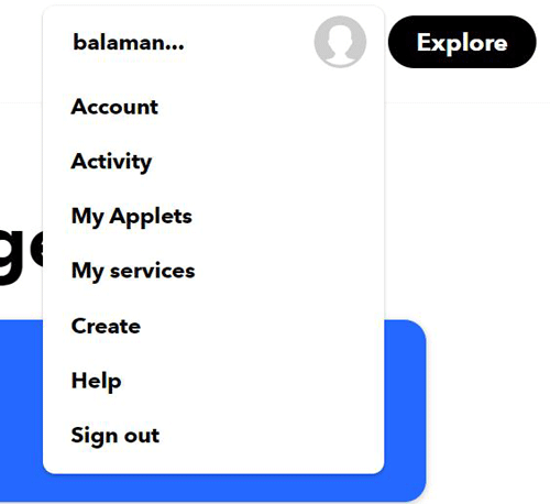
To create an account on IFTTT, navigate to the IFTTT website and click on signup. Then fill out the required details like email, password, etc. After creating and signing up to your account, click on the profile and then click on ‘Create’.
After clicking on the ‘create’, a page will be loaded saying ‘Create your own If This Then That’. Here the ‘This’ is the service name, which will act as an input to the condition, and ‘That’ is the action, which triggers according to the input. So in our project, the input will be Google Assistant, and the action will be taking place on Adafruit IO. Now to create an applet, click on the ‘This’ icon. Search for Google assistant.

After selecting Google Assistant in step 2, click on ‘Say a simple phrase’.
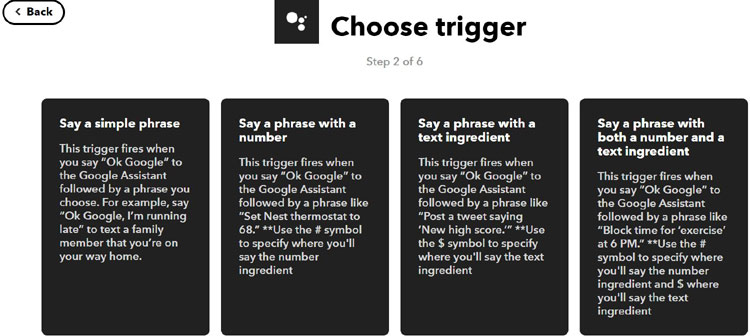
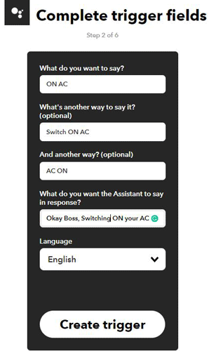
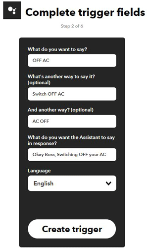
In the next window, a window will pop up saying ‘complete the trigger fields’ i.e. the phrase (ON AC) that you want to say to your google assistant, which will trigger an action. There are also some optional phrases that you can add. After filling the fields, click on ‘create trigger’. The input part is done.
Now, we have to set the ‘That’ (Action) part. Click on ‘That’.

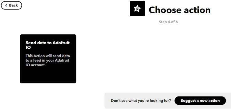
Select Adafruit by searching it in the action service search bar.

Now, select Send data to Adafruit IO.
A window will be loaded where you will have to select your feed name(VoiceAC) for which you want to create a trigger. In the next field, enter the data(ON) which you want to enter into the feed when you say your specified phrase.
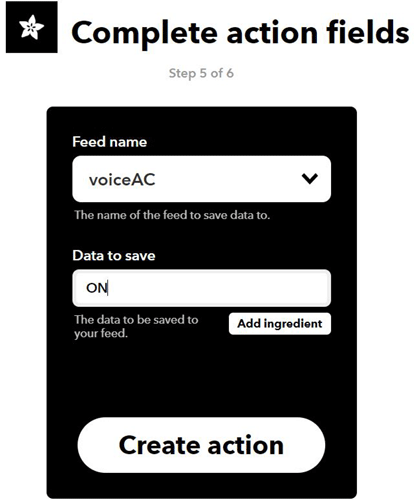
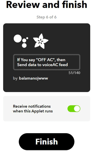
After this, click on ‘Create action’. By clicking on the finish button, your applet is ready to use.
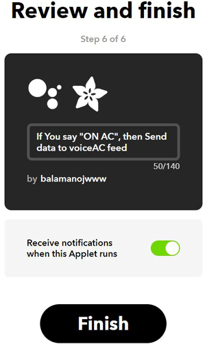
By now, we created an applet that triggers when we say ON AC to our google assistant. Now, we are going to create an applet which triggers when we say OFF AC to our google assistant. Continue the same procedure from above, the only difference will be in step 2 and step 5. In the fields in step 2, instead of writing ON AC we are going to write OFF AC phrase.
In step 5, the feed name will be the same as before, but the Data to save the field will be changed to OFF.

By clicking on the ‘Create action’, you have successfully created another applet, which will be triggered by the phrase ‘OFF AC’
Code Explanation for Voice-controlled AC using Google Assistant
We are going to write our code keeping in mind that at first when we press the push button 1 or push button 2, it has to capture the incoming signals. After capturing the incoming signals, we need to write the code which deals with the communication with our google assistant and NodeMCU and then mimic those signals through IR blaster. The main code for our project is given at the end of this article. So, here I am just going to explain our code.
Along with the library which you downloaded using the above link, you have to download Adafruit MQTT Library by Adafruit by using library Manager. Defining the pins D7 and D8 of the NodeMCU are ON_B and OFF_B. These pins are used to enter into a loop that is used to capture the IR signal. These pins are by default LOW and if these are high, the loop will be activated.
#defineON_B D7
#define OFF_B D8
The code given below defines a variable to the address, names, port number, passcode, SSID, and wifi password. The server address and the port number can be as it is, but you have to change the MQTT NAME and MQTT PASS, which you got in the AIO key.
#define MQTT_SERV "io.adafruit.com"
#define MQTT_PORT 1883
#define MQTT_NAME "Manu_bala"
#define MQTT_PASS "aio_aGqm70ciSezxtnUYtWQtQPzNDq0X"
#define WIFI_SSID "CIRCUIT"
#define WIFI_PASS "1234567890"
WiFiClient client;
We are assigning pin 4 (D2) and pin 14(D5) to klrLed and kRecvPin variables and using D2 pin to send IR data while D5 pin is used to receive IR data
const uint16_t kIrLed = 4;
IRsend irsend(kIrLed);
const uint16_t kRecvPin = 14;
IRrecv irrecv(kRecvPin, kCaptureBufferSize, kTimeout, true);
Inside the void setup, we initialized the baud rate and had to wait for the microcontroller to form a serial connection. The serial communication is used for debugging purpose. After establishing the connection, we are setting the pins D7(ON_B) and D8(OFF_B) as input pins and D4 pin as an output. The pins D7 and D8 are used to find whether the switch connected to these pins are in ON state or OFF state. The pin D4 is used to connect with an LED, which is further used as an indicator. After configuring these pins as input and output pins, we are establishing a connection with the home network. After the connection is established, we are subscribing to the VoiceAC feeder through the MQTT protocol and initializing the sending function through irsend.begin.
void setup() {
#if defined(ESP8266)
  Serial.begin(kBaudRate, SERIAL_8N1, SERIAL_TX_ONLY);
#else  // ESP8266
  Serial.begin(kBaudRate, SERIAL_8N1);
#endif  // ESP8266
  while (!Serial)  // Wait for the serial connection to be established.
    delay(50);
  Serial.printf("\n" D_STR_IRRECVDUMP_STARTUP "\n", kRecvPin);
pinMode(ON_B,INPUT);
pinMode(OFF_B,INPUT);
pinMode(D4, OUTPUT);
Serial.print("\n\nConnecting Wifi... ");
WiFi.begin(WIFI_SSID, WIFI_PASS);
while (WiFi.status() != WL_CONNECTED)
{
    delay(500);
}
 mqtt.subscribe(&voiceAC);
 irsend.begin();
}
The code is given below deals with the MQTT connection. The main program for the MQTT connection is written in a separate function and that function is named MQTT_connect(). The MQTT program is called using the MQTT_connect() function which is present in the void loop.
MQTT_connect();
void MQTT_connect()
{
  int8_t ret;
  if (mqtt.connected())
  {
    return;
  }
  uint8_t retries = 3;
  while ((ret = mqtt.connect()) != 0) // connect will return 0 for connected
  {
       mqtt.disconnect();
       delay(5000);  // wait 5 seconds
       retries--;
       if (retries == 0)
       {
         while (1);
       }
  }
}
The code given below contains two main ‘if’ conditions. If the ON_B pin is high, the first ‘if’ condition will be activated, and the code is written inside the first ‘if’ loop will run. If the OFF_B pin is high, the second ‘if’ condition will be activated, and the code is written inside the second ‘if’ loop will run.
if(digitalRead(ON_B) == HIGH){
if the ON_B pin is high, the code will enter into the loop. The D4 pin will glow high indicating that the program has entered the loop and waiting for the user to initialize the ON IR data using an AC remote.
digitalWrite(D4, HIGH);
The code will be in an infinite loop until the user gives the correct IR code through an IR remote. The function resultToHumanReadableBasic(&results) returns “UNKNOWN” if the data is corrupted due to noise. If the resultToHumanReadableBasic(&results) returns any string apart from “UNKNOWN”, it means that the data is correct and is without noise. This will make the program exit from the while loop and proceed for the next instruction.
    int v = 0;
    while(! irrecv.decode(&results) || v == 0){
      if(resultToHumanReadableBasic(&results) != "UNKNOWN\n"){
        v=1;
      }
      yield();
    }
The indicator LED, which is connected to the D4 pin will be switched off, indicating that the user has sent the correct IR data to the MCU.
digitalWrite(D4, LOW);
The code given below is used to convert the string values, which is returned by the resultToSourceCode(&results) function into uint_16 type. I have first stored the result (resultToSourceCode(&results)) in the x variable, which is a string type. Each data is divided by a comma, so I kept on checking each character in the variable x using a while loop. If the character inside the x variable is not a comma “,”, then that character is added to a string variable called convert. This continues until there is an “,”. If there is a character “,”, it means that data has been finished storing in the string variable convert. The first data stored in the converted variable will always be the size of the data. So at first, I stored that data in a size1 variable, which is an int. after the first variable gets stored in the size1 variable, we have to empty the “convert” variable for the next process and make it ready to store the fresh data again. When the program senses a second “,”, we know that it is the data that we needed to send through the IR Blaster.
So, we wrote the program in such a way that the first incoming data will be stored in the size1 variable and the remaining data will be stored in the variable “rawData1”. We are using convert.toInt() to convert the string into an int, and then stored that data in the variable. This procedure carries on until each data inside the x variable is completely stored in the “rawData” variable.
     if(resultToHumanReadableBasic(&results) != "UNKNOWN\n"){
      Serial.println("Working");
    String description = IRAcUtils::resultAcToString(&results);
    if (description.length()) Serial.println(D_STR_MESGDESC ": " + description);
    yield();  // Feed the WDT as the text output can take a while to print.
#if LEGACY_TIMING_INFO
    // Output legacy RAW timing info of the result.
    Serial.println(resultToTimingInfo(&results));
    yield();  // Feed the WDT (again)
#endif  // LEGACY_TIMING_INFO
 the results as source code
    Serial.println("Start");
    x = (resultToSourceCode(&results));
    Serial.print(x);
    i=0;
    j=0;
    size1 = 0;
    while( x[i] != '\n'){
      if(x[i]!= ','){
        convert = convert + x[i];
      }
      else if(size1 == 0) {
        size1 = convert.toInt();
        Serial.println(size2);
        convert = "";
      }
      else {
        rawData1[j] = convert.toInt();
        Serial.println(rawData1[j]);
        convert = "";
        j++;
      }
      i++;
    }
    rawData1[j] = convert.toInt();
    Serial.println("End");
    Serial.print(rawData1[j]);
        convert = "";
    yield();  // Feed the WDT (again)
         Serial.println("ON");
     Serial.println(size1);
  }
  }
This “if” condition checks whether the OFF_B pin is HIGH or Low. If it is HIGH, the program enters the loop. The code inside the “if” condition is the same as above but with small changes in the variables used. In the above code, we used the variables rawData1 and size1 but in this loop, we will be using the variables rawData2 and size2.
 if(digitalRead(OFF_B) == HIGH){
}
The below code deals with the communication between the MCU and Adafruit IO servers. The if condition if (!strcmp((char*) voiceAC.lastread, "ON")) will be true only if the user uses the specified phrase through the google assistant. The function irsend.sendRaw() is used to send the raw data of the specified size with 38KHz frequency upon matching of the phrase.
Adafruit_MQTT_Subscribe * subscription;
while ((subscription = mqtt.readSubscription(5000)))
  {
if (subscription == &voiceAC)
    {
      //Print the new value to the serial monitor
      Serial.println((char*) voiceAC.lastread);
             if (!strcmp((char*) voiceAC.lastread, "ON"))
             {
              Serial.println((char*) voiceAC.lastread);
              Serial.println("Switching ON AC");
              irsend.sendRaw(rawData1, size1, 38);  // Send a raw data capture at 38kHz.
              Serial.println("Size1 =");
              Serial.println(size1);
              }
              else if (!strcmp((char*) voiceAC.lastread, "OFF"))
             {
              Serial.println((char*) voiceAC.lastread);
              Serial.println("Switching OFF AC");
              irsend.sendRaw(rawData2, size2, 38);  // Send a raw data capture at 38kHz.
              Serial.println("Size2 =");
              Serial.println(size2);
              }
    }
  }
}
Working of IoT Based Universal AC Remote
We wrote our program in such a way that at first, we have to capture the data, which is emitted from an AC remote. We are doing that by using a TSOP1738 IR receiver. After capturing the signals, we are going to store that data in a variable, and mimic those signals using an IR blaster when desired.
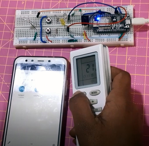
When we switch on the supply, we will notice that the indicator LED (Green LED) will be blinking. This is to indicate that the module is waiting for a wifi connection. If the indicator LED stops blinking, it means that the nodeMCU has been connected to the wifi network. After establishing a connection to a network, to capture the IR data, keep on Pressing the button(ON_B or OFF_B), which is connected to the D7 or D8 until the indicator LED starts glowing. The glowing of the indicator LED indicates that the nodeMCU is ready for capturing the IR data. Use your AC remote to send the IR signal to our TSOP as shown below. If the IR data is correct without any noise, the indicator stops glowing, indicating that NodeMCU has captured the IR data successfully and can mimic the data again.
The same procedure is followed for another remaining button. As I said earlier, we are going to only deal with the switching ON or switching OFF of the AC. ON_B button is used to capture the data required to switch ON the AC and the OFF_B button is used to capture the data required to switch OFF the AC. After capturing both data, place the module in front of the AC.
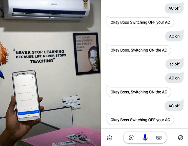
After this, you can just sit, and command your google assistant to Switch ON or OFF the AC. If you want, you can even upgrade this module to capture the temperature or fan mode, etc. and control those parameters.
#include <Arduino.h>
#include <IRrecv.h>
#include <IRremoteESP8266.h>
#include <IRac.h>
#include <IRtext.h>
#include <IRutils.h>
#define ON_B D7
#define OFF_B D8
#include <ESP8266WiFi.h>
#include "Adafruit_MQTT.h"
#include "Adafruit_MQTT_Client.h"
#include<Servo.h>
#include <WiFiUdp.h>
#include <Wire.h>
#define MQTT_SERV "io.adafruit.com"
#define MQTT_PORT 1883
#define MQTT_NAME "Manu_bala"
#define MQTT_PASS "aio_aGqm70ciSezxtnUYtWQtQPzNDq0X"
#define WIFI_SSID "CIRCUIT"
#define WIFI_PASS "1234567890"
WiFiClient client;
Adafruit_MQTT_Client mqtt(&client, MQTT_SERV, MQTT_PORT, MQTT_NAME, MQTT_PASS);
Adafruit_MQTT_Subscribe voiceAC = Adafruit_MQTT_Subscribe(&mqtt, MQTT_NAME "/f/voiceAC");
String x= "", convert = "";
int i = 0,j = 0, len = 0, m = 0, size1= 0, size2 = 0;
#ifndef UNIT_TEST
#endif
#include <IRsend.h>
const uint16_t kIrLed = 4;
IRsend irsend(kIrLed);
uint16_t rawData2 [200] = {};
uint16_t rawData1 [200] = {};
const uint16_t kRecvPin = 14;
const uint32_t kBaudRate = 115200;
const uint16_t kCaptureBufferSize = 1024;
#if DECODE_AC
const uint8_t kTimeout = 50;
#else // DECODE_AC
const uint8_t kTimeout = 15;
#endif // DECODE_AC
const uint16_t kMinUnknownSize = 12;
#define LEGACY_TIMING_INFO false
IRrecv irrecv(kRecvPin, kCaptureBufferSize, kTimeout, true);
decode_results results; // Somewhere to store the results
// This section of code runs only once at start-up.
void setup() {
#if defined(ESP8266)
Serial.begin(kBaudRate, SERIAL_8N1, SERIAL_TX_ONLY);
#else // ESP8266
Serial.begin(kBaudRate, SERIAL_8N1);
#endif // ESP8266
while (!Serial) // Wait for the serial connection to be establised.
delay(50);
Serial.printf("\n" D_STR_IRRECVDUMP_STARTUP "\n", kRecvPin);
pinMode(ON_B,INPUT);
pinMode(OFF_B,INPUT);
pinMode(D4, OUTPUT);
Serial.print("\n\nConnecting Wifi... ");
WiFi.begin(WIFI_SSID, WIFI_PASS);
while (WiFi.status() != WL_CONNECTED)
{
delay(500);
}
mqtt.subscribe(&voiceAC);
irsend.begin();
Serial.println("OK!");
#if DECODE_HASH
// Ignore messages with less than minimum on or off pulses.
irrecv.setUnknownThreshold(kMinUnknownSize);
#endif // DECODE_HASH
irrecv.enableIRIn(); // Start the receiver
}
// The repeating section of the code
void loop() {
MQTT_connect();
if(digitalRead(ON_B) == HIGH){
digitalWrite(D4, HIGH);
int v = 0;
// turn the LED on (HIGH is the voltage level)
while(! irrecv.decode(&results) || v == 0){
if(resultToHumanReadableBasic(&results) != "UNKNOWN\n"){
v=1;
}
yield();
}
digitalWrite(D4, LOW);
if(resultToHumanReadableBasic(&results) != "UNKNOWN\n"){
Serial.println("Working");
// Display any extra A/C info if we have it.
String description = IRAcUtils::resultAcToString(&results);
if (description.length()) Serial.println(D_STR_MESGDESC ": " + description);
yield(); // Feed the WDT as the text output can take a while to print.
#if LEGACY_TIMING_INFO
// Output legacy RAW timing info of the result.
Serial.println(resultToTimingInfo(&results));
yield(); // Feed the WDT (again)
#endif // LEGACY_TIMING_INFO
// Output the results as source code
Serial.println("Start");
x = (resultToSourceCode(&results));
Serial.print(x);
i=0;
j=0;
size1 = 0;
while( x[i] != '\n'){
if(x[i]!= ','){
convert = convert + x[i];
}
else if(size1 == 0) {
size1 = convert.toInt();
Serial.println(size2);
convert = "";
}
else {
rawData1[j] = convert.toInt();
Serial.println(rawData1[j]);
convert = "";
j++;
}
i++;
}
rawData1[j] = convert.toInt();
Serial.println("End");
Serial.print(rawData1[j]);
convert = "";
yield(); // Feed the WDT (again)
Serial.println("ON");
Serial.println(size1);
}
}
if(digitalRead(OFF_B) == HIGH){
int v = 0;
digitalWrite(D4, HIGH); // turn the LED on (HIGH is the voltage level)
while(! irrecv.decode(&results) || v == 0){
if(resultToHumanReadableBasic(&results) != "UNKNOWN\n"){
v=1;
}
yield();
}
digitalWrite(LED_BUILTIN, LOW); // turn the LED off by making the voltage LOW
// uint16_t rawData2 [200] = {};
if(resultToHumanReadableBasic(&results) != "UNKNOWN\n"){
Serial.println("Working");
// Display any extra A/C info if we have it.
String description = IRAcUtils::resultAcToString(&results);
if (description.length()) Serial.println(D_STR_MESGDESC ": " + description);
yield(); // Feed the WDT as the text output can take a while to print.
#if LEGACY_TIMING_INFO
// Output legacy RAW timing info of the result.
Serial.println(resultToTimingInfo(&results));
yield(); // Feed the WDT (again)
#endif // LEGACY_TIMING_INFO
// Output the results as source code
Serial.println("Start");
x = (resultToSourceCode(&results));
Serial.print(x);
i=0;
j=0;
size2 = 0;
while( x[i] != '\n'){
if(x[i]!= ','){
convert = convert + x[i];
}
else if(size2 == 0) {
size2 = convert.toInt();
Serial.println(size2);
convert = "";
}
else {
rawData2[j] = convert.toInt();
Serial.println(rawData2[j]);
convert = "";
j++;
}
i++;
}
rawData2[j] = convert.toInt();
Serial.println("End");
Serial.print(rawData2[j]);
convert = "";
yield(); // Feed the WDT (again)
Serial.println("OFF");
Serial.println(size2);
}
}
Adafruit_MQTT_Subscribe * subscription;
while ((subscription = mqtt.readSubscription(5000)))
{
if (subscription == &voiceAC)
{
//Print the new value to the serial monitor
Serial.println((char*) voiceAC.lastread);
if (!strcmp((char*) voiceAC.lastread, "ON"))
{
Serial.println((char*) voiceAC.lastread);
Serial.println("Switching ON AC");
irsend.sendRaw(rawData1, size1, 38); // Send a raw data capture at 38kHz.
Serial.println("Size1 =");
Serial.println(size1);
}
else if (!strcmp((char*) voiceAC.lastread, "OFF"))
{
Serial.println((char*) voiceAC.lastread);
Serial.println("Switching OFF AC");
irsend.sendRaw(rawData2, size2, 38); // Send a raw data capture at 38kHz.
Serial.println("Size2 =");
Serial.println(size2);
}
}
}
}
void MQTT_connect()
{
int8_t ret;
// Stop if already connected.
if (mqtt.connected())
{
return;
}
uint8_t retries = 3;
while ((ret = mqtt.connect()) != 0) // connect will return 0 for connected
{
mqtt.disconnect();
delay(5000); // wait 5 seconds
retries--;
if (retries == 0)
{
// basically die and wait for WDT to reset me
while (1);
}
}
}


