


In this blog, we will learn about interfacing the Servo motor with Raspberry Pi Pico W and programming it with Arduino IDE. Generally, the Micropython used to program the Pico W but we will learn about programming in C/C++. The Raspberry Pi Pico W is a great board for those who are looking for a powerful and versatile microcontroller that is easy to use and affordable.
Learn more about Raspberry Pi Pico W by going through previous tutorials:
- Interfacing OLED Display with Raspberry Pi Pico W using Arduino IDE
- Interfacing Servo Motor with Raspberry Pi Pico W using Arduino IDE
- Build your own Weather Station using Raspberry Pi Pico W
- Controlling an LED using Raspberry Pi Pico W based Webserver
Arduino IDE is a highly effective and time-saving programming tool for beginners. It is widely used and familiar to most beginners, has a large library ecosystem, and does not require any other software installation.
The interfacing allows us to control the movements of the servo using the PWM-enabled GPIO pins of the Pico W. The Raspberry Pi Pico w is an affordable programmer board that uses an RP2040 microcontroller.
Components Required
- Servo Motor (SG-90)
- Raspberry Pi Pico W Board
- Jumper Wires & Breadboard
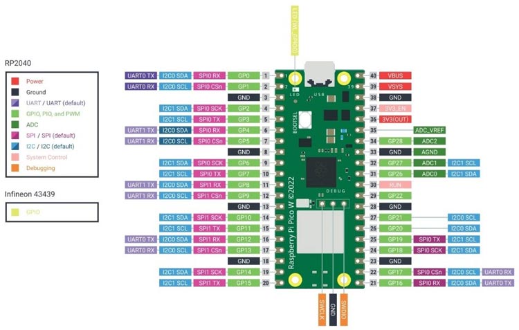
Pinout of Raspberry Pi Pico W
The board has a built-in future of Wi-Fi and Bluetooth compatibility, making it a perfect solution for various IoT-controlled wireless devices and projects. It has 26 GPIO pins, 264kB of SRAM, 2MB of onboard flash memory, and an RP2040 chip-based Microcontroller. The other pins include Power, GND, and Reference pins.
Servo Motor (SG-90) Working
The SG 90 servo motor is a widely utilized Servo, offering a rotational angle range of 0 to 180 degrees. This Servo Motor operates through the PWM technique, enabling us to manipulate the angular position of the output Shaft by adjusting its duty cycle. As a result, these Motors find extensive application in precisely controlling angular motion for a variety of purposes, including RC cars, robotic arms, and CNC machines.
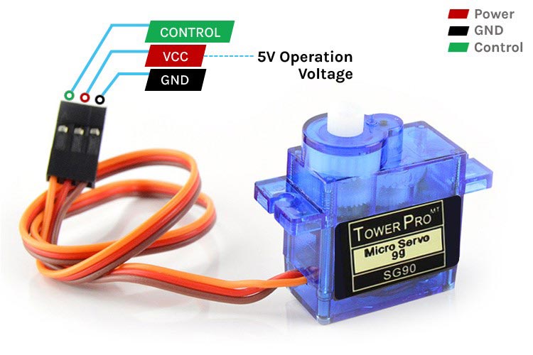
The connection of the Servo typically includes three pins:
VCC (or +): This pin is connected to the positive terminal of the power supply (typically 4.8V to 6V). It provides the operating voltage for the servo motor.
GND (or -): This pin is connected to the ground (0V) of the power supply, completing the electrical circuit.
Signal (or control) pin: The pin uses the control signal generated from the microcontroller in the form of PWM (Pulse width modulation). The pin must be connected to the PWM pin of the Board. The control signal determines the position or angle at which the servo should rotate.
Circuit Diagram of Interfacing Servo with Raspberry Pi Pico W
The below diagram describes the connections to interface the servo with the Pico W board.
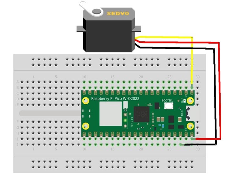
The Vcc or power pin of the servo should be connected to the VBUS pin of the Raspberry Pi Pico W.
The GND of the Servo is connected to any Ground terminal of the Pico Board. Since there are various ground terminals on the board, you can use any of them.
The Signal Pin of the Servo must be connected to any PWM-enabled GPIO of the Pico W. Mostly All the GPIO pins are PWM enabled in Pico W from GP0 – GP28.
Arduino Code for interfacing Servo with Raspberry Pi Pico W
The code part is quite simple, as we have to use the necessary libraries first which include Servo.h to control the rotation of the servo.
The code commands the servo to control the angular rotation of 0 to 180 degrees and Vice-Versa.
#include <Servo.h>
#define PIN_SG90 0 // Output pin used
Servo myservo;      // create servo object to control a servo
Inside the Setup() function, given the signal pin details of the Servo attached to the board into the attach() function to the object myservo. I have attached the Signal pin of the Servo to the GP-0 pin of the Pico board. Also, the attach() function is used to specify the pin and the minimum and maximum pulse width values in microseconds required to rotate the servo from 0° to 180°. In this case, the minimum pulse width is set to 400 µs, and the maximum pulse width is set to 2600 µs.
void setup() {
  myservo.attach(PIN_SG90, 400, 2600); // Minimum and maximum pulse width (in µs) to go from 0° to 180°.
}
Inside the loop() function, using the two for loops we have created the code designs so that the first “for” loop provides rotation from 0 to 180 degrees and the second one will reverse back position to zero. The loop will run for infinite times.
void loop() {
 // Rotation from 0 to 180°.
  for (int Angle = 0; Angle <= 180; Angle += 1) {
    myservo.write(Angle);
    delay(10);
  }
 // Rotation from 180° to 0.
  for (int Angle = 180; Angle >= 0; Angle -= 1) {
    myservo.write(Angle);
    delay(10);
  }
}
Overall, the code will continuously rotate the servo motor back and forth between 0° and 180° with a delay of 10 milliseconds between each step.
Working of Servo with Raspberry Pi Pico W
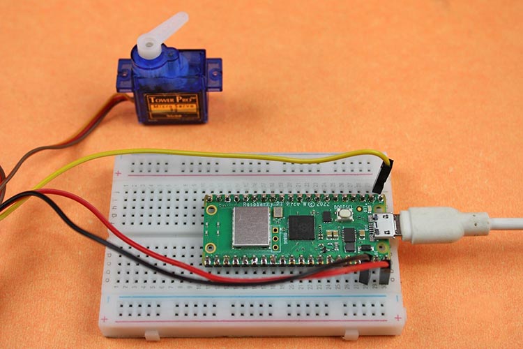
To upload the code to Raspberry Pi Pico w we have to install the board library to our Arduino IDE. Here is the tutorials present of previously designed projects of Raspberry Pi Pico W, you can refer to them for step-by-step procedures of installation.
Finally, upload the whole code by carefully following the procedure in the tutorial & make sure to check for the correct hardware pin inside the code.
Hope you enjoyed the article and learned something useful from it. If you have any questions, you can leave them in the comment section below.
#include <Servo.h>
#define PIN_SG90 0 // Output pin used
Servo myservo; // create servo object to control a servo
void setup() {
myservo.attach(PIN_SG90, 400, 2600); // Minimum and maximum pulse width (in µs) to go from 0° to 180°.
}
void loop() {
// Rotation from 0 to 180°.
for (int Angle = 0; Angle <= 180; Angle += 1) {
myservo.write(Angle);
delay(10);
}
// Rotation from 180° to 0.
for (int Angle = 180; Angle >= 0; Angle -= 1) {
myservo.write(Angle);
delay(10);
}
}


