


Hello guys, in this project we are going to learn about Interfacing an ultrasonic sensor with the Raspberry Pi Pico W using the Arduino IDE which combines the power of the Pico W microcontroller board with the ease of programming provided by the Arduino development environment. Using the Arduino IDE provides a straightforward approach to programming development boards using C/C++.
This project gives you an insight of measuring distances using an ultrasonic sensor which can be used to perform various actions based on the detected distance. By utilizing the capabilities of the Raspberry Pi Pico W and the simplicity of the Arduino IDE, you can create a range of applications such as distance monitoring, object detection, and obstacle avoidance systems. Let's explore how to set up and program this project to unlock its potential in your applications.
Learn more about Raspberry Pi Pico W by going through previous tutorials:
- Interfacing OLED Display with Raspberry Pi Pico W using Arduino IDE
- Interfacing Servo Motor with Raspberry Pi Pico W using Arduino IDE
- Build your own Weather Station using Raspberry Pi Pico W
- Controlling an LED using Raspberry Pi Pico W based Webserver
Components Required
- Ultrasonic Sensor Module
- Raspberry Pi Pico W Board
- Jumper Wires & Breadboard
Ultrasonic Sensor Module
The Ultrasonic Sensor operates by utilizing sound waves to calculate the distance of an object, making it an effective distance-measuring sensor. It consists of two Ultrasonic Transducers, with one functioning as a transmitter, emitting a high-frequency Ultrasonic signal. The other transducer acts as a receiver, detecting the echo signal reflected by any object in its path. Ultrasonic Sensors are cost-effective, simple to interface with, and have low power requirements. They can also be employed to measure water depth, as sound waves can propagate through water.
The range of measuring the distance is about 2cm to 400cm. The basic principle of working is:
- Trigger pin should have a High-level signal for at least 10us.
- The Module automatically sends eight 40 kHz frequency signals through the transmitter and the echo pin goes high as soon as the pulse is transmitted and goes low as soon as the pulse is received.
- If the signal is back then, the echo pin's high-level time is the duration from sending to returning ultrasonic pulse.
Distance Calculation: The time duration taken by the wave to travel the distance is measured by the controller IC. Hence the distance traveled by the wave is calculated by multiplication of the speed of sound (340m/s) with the time duration of the wave. Half of the total distance traveled by the wave is the Actual distance of the object from the sensor.
Object Distance= (time duration x speed of sound (340 m/s)) / 2
Ultrasonic Sensor Module Pinout
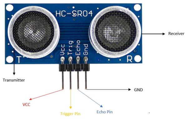
There are four terminals for the connection of the ultrasonic sensor:
VCC (Power Supply): This pin is connected to the power supply, usually 5V. It provides the necessary voltage for the ultrasonic sensor to function.
GND (Ground): The GND pin is connected to the ground or 0V reference of the power supply.
TRIG (Trigger): The TRIG pin is an input pin that triggers the ultrasonic sensor to send out an ultrasonic pulse of 10µs. You typically send a short high-level pulse to this pin to initiate a distance measurement.
ECHO (Echo): The ECHO pin is an output pin that senses the ultrasonic pulse after it reflects off an object. By measuring the duration of the high level on this pin, you can calculate the distance to the object.
Circuit Diagram - Interfacing Ultrasonic Sensor with Raspberry Pi Pico W
The Raspberry Pi Pico W board offers multiple GPIO digital pins, since the trig & echo are digital pins, hence you can use any of the digital pins on board. For its compatibility and pinouts, you can refer to the previously created Blog on Raspberry Pi Pico W. The below circuit diagram helps you to better understand the connections.
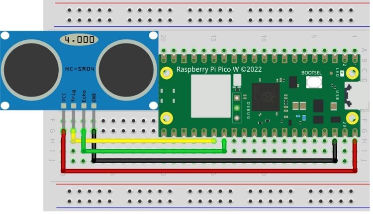
The Vcc or power pin of the Ultrasonic should be connected to the VBUS pin of the Raspberry Pi Pico W whose supply voltage is 5v.
The GND of the Ultrasonic is connected to any Ground terminal of the Pico Board. Since there are various ground terminals on the board, you can use any of them.
The Trig pin of the sensor is connected to the digital pin GP20 of the Pico board.
The Echo pin is connected to the GP21 of the Pico Board.
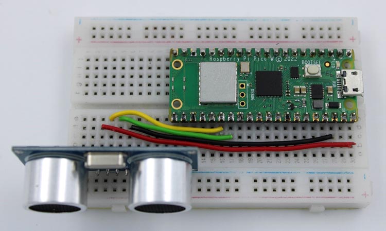
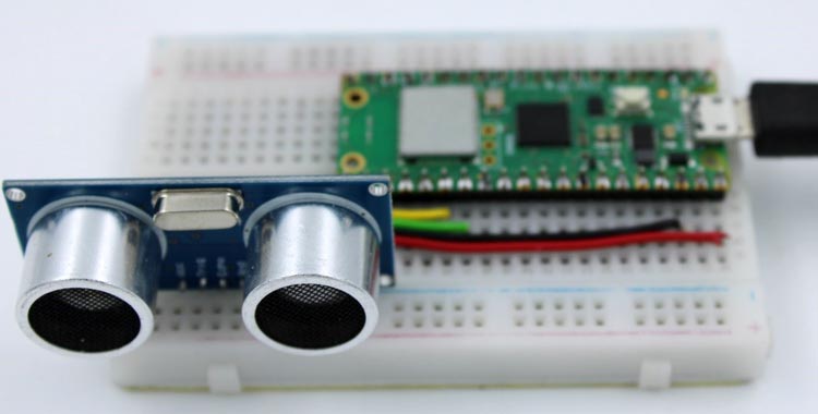
The real interface will something looks like this:
Code for interfacing Ultrasonic Sensor with Raspberry Pi Pico W
This code uses sensor to measure distance and display the measured distance in centimeters to the serial monitor.
The program sets the digital pins for interfacing the sensor with the Pico W board as we know there are two digital pins on ultrasonic for communication. Also, we have defined some necessary variables for storing the data in further programming.
#define trigger 20
#define echo 21
float duration=0,distance=0;
Inside the setup() function, the following actions were performed:
Initializing the serial communication and setting the pin mode for the digital communication pins. In this case, the trig pin necessitates a HIGH signal from the board, while Echo provides its high time, which is utilized for calculations. As a result, the trig pin is set as an output to send the signal, while the Echo pin is set as an input to receive the high time.
void setup()
{Serial.begin(115200);
 pinMode(trigger,OUTPUT);
 pinMode(echo,INPUT);
 delay(1000);
}
Inside the loop() function, as we know the trig pin should be HIGH for 10µs to transmit the pulses. Hence,
- The trigger pin is set to LOW to ensure it's in a known state.
- With a delay of 2 microseconds the trigger pin is set to HIGH for 10 microseconds to send an ultrasonic pulse.
- The trigger pin is set back to LOW.
The pulseIn() function is used to measure the duration it takes for the ultrasonic pulse to return. It measures the duration for which the echo pin Stays HIGH and then returns the duration in microseconds.
The distance is simply calculated by multiplying the duration (in µs) by the speed of sound (approximately 340 meters per second) and dividing it by 2 because the pulse traveled twice the distance to the object and back. Since the time duration is in µs, hence to convert speed (340 m/s) to µs we also divided the equation by 10^4.
The calculated distance is printed on the serial monitor in centimeters.
void loop()
{digitalWrite(trigger,LOW);
 delayMicroseconds(2);
 digitalWrite(trigger,HIGH);
 delayMicroseconds(10);
 digitalWrite(trigger,LOW);
 duration=pulseIn(echo,HIGH);
 distance=duration*340/20000;
 Serial.print(distance);
 Serial.println("cm");
 delay(500);
}
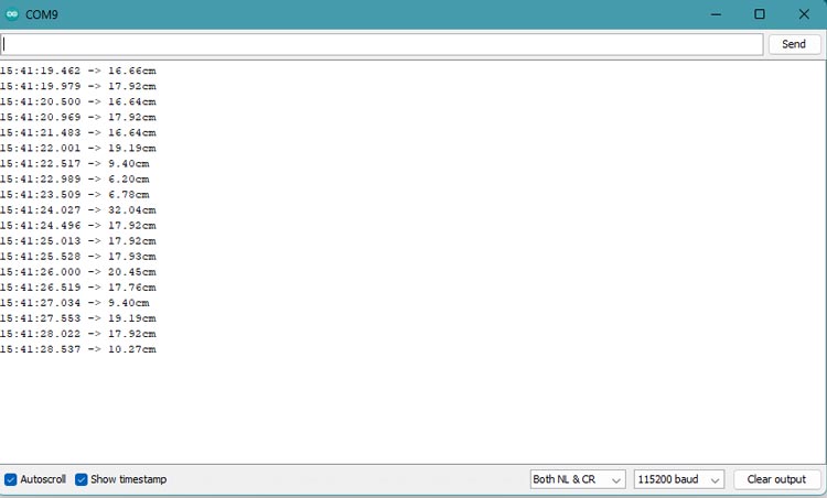
The code continuously repeats this process, measuring the distance and displaying it on the serial monitor every 0.5 seconds.
Working of Ultrasonic with Raspberry Pi Pico W
Uploading code to Raspberry Pi Pico W requires board installation in Arduino IDE. Upload the Code to the Pico W board, before that check for the proper hardware connections.
Now, open the Serial Monitor, and you will see the distance measurements printed in centimeters.
Hope you enjoyed the article and learned something useful from it. If you have any questions, you can leave them in the comment section below.
#define trigger 20
#define echo 21
float duration=0,distance=0;
void setup() {
Serial.begin(115200);
pinMode(trigger,OUTPUT);
pinMode(echo,INPUT);
delay(1000);
}
void loop() {
digitalWrite(trigger,LOW);
delayMicroseconds(2);
digitalWrite(trigger,HIGH);
delayMicroseconds(10);
digitalWrite(trigger,LOW);
duration=pulseIn(echo,HIGH);
distance=duration*340/20000;
Serial.print(distance);
Serial.println("cm");
delay(500);
}


